Nissan Juke Service and Repair Manual : Side oil seal
Exploded View
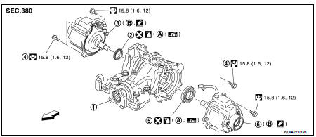
1. Rear final drive assembly
2. Side oil seal (right)
3. Electric controlled coupling (right)
4. Reamer bolt
5. Side oil seal (left)
6. Electric controlled coupling (left)
A. Oil seal lip B. Gear carrier mouting face
 : Vehicle front
 : N·m (kg-m, ft-lb)
 : Always replace after every
disassembly.
 : Apply multi purpose grease
 : Apply gear oil.
 : Apply Genuine Liquid Gasket 1217
or equivalent.
Removal and Installation
REMOVAL
1. Remove electric controlled couplings. Refer to DLN-139, "Removal and Installation".
2. Remove side oil seals with a suitable tool.
CAUTION:
Never damage gear carrier and rear cover.

INSTALLATION
1. Install side oil seal (right side) until it becomes flush with the carrier end, using the drift (A) (SST: KV38100200).
CAUTION:
• Never reuse oil seals.
• When installing, never incline oil seals.
• Apply multi-purpose grease onto oil seal lips, and gear oil onto the circumference of oil seal
.

2. Install side oil seal (left side) until it becomes flush with the carrier end, using the drift (A) (SST: KV38100500).
CAUTION:
• Never reuse oil seals.
• When installing, never incline oil seals.
• Apply multi-purpose grease onto oil seal lips, and gear oil onto the circumference of oil seal.
3. Install electric controlled couplings. Refer to DLN-139, "Removal and Installation".
4. When oil leaks while removing, check oil level after the installation.
Refer to DLN-132, "Inspection".

 Front oil seal
Exploded View
1. Rear final drive assembly
2. Front oil seal
3. Companion flange
4. Companion flange lock nut
A. Oil seal lip
: Vehicle front
: N·m (kg-m, ft-lb)
: Never reuse parts
: App ...
 Electric controlled coupling
Exploded View
1. Sub-harness
2. Rear final drive assembly
3. Electric controlled coupling (right)
4. Reamer bolt
5. Electric controlled coupling (left)
A. Gear carrier mouting face
: Vehic ...
Other materials:
B2618 BCM
DTC Logic
DTC DETECTION LOGIC
NOTE:
• If DTC B2618 is displayed with DTC U1000, first perform the trouble diagnosis
for DTC U1000. Refer to
BCS-83, "DTC Logic".
• If DTC B2618 is displayed with DTC U1010, first perform the trouble diagnosis
for DTC U1010. Refer to
BCS-84, "D ...
P1864 input speed signal
DTC Logic
DTC DETECTION LOGIC
DTC CONFIRMATION PROCEDURE
1.PRECONDITIONING
If “DTC CONFIRMATION PROCEDURE” has been previously conducted, always turn
ignition switch OFF and
wait at least 10 seconds before conducting the next test.
>> GO TO 2.
2.DTC REPRODUCTION PROCEDURE
With ...
Precaution Necessary for Steering Wheel Rotation after Battery Disconnect
NOTE:
• Before removing and installing any control units, first turn the ignition
switch to the LOCK position, then disconnect
both battery cables.
• After finishing work, confirm that all control unit connectors are connected
properly, then re-connect both
battery cables.
• Always use CONS ...