Nissan Juke Service and Repair Manual : Security indicator lamp
Component Function Check
1.CHECK FUNCTION
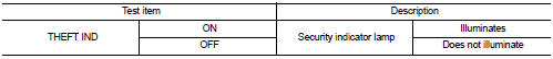
1. Perform “THEFT IND” in the “ACTIVE TEST” mode of “BCM” using CONSULT-III.
2. Check security indicator lamp operation.
Is the inspection result normal? YES >> INSPECTION END
NO >> Go to SEC-227, "Diagnosis Procedure".
Diagnosis Procedure
1.CHECK SECURITY INDICATOR LAMP POWER SUPPLY CIRCUIT
1. Turn ignition switch OFF.
2. Disconnect combination meter connector.
3. Check voltage between combination meter harness connector and ground.

Is the inspection result normal? YES >> GO TO 2.
NO-1 >> Check 10 A fuse [No. 11, located in the fuse block (J/B)].
NO-2 >> Check harness for open or short between combination meter and fuse.
2.CHECK SECURITY INDICATOR LAMP SIGNAL
1. Connect combination meter connector.
2. Disconnect BCM connector.
3. Check voltage between BCM harness connector and ground.

Is the inspection result normal? YES >> Replace BCM. Refer to BCS-161, "Removal and Installation".
NO >> GO TO 3.
3.CHECK COMBINATION METER CIRCUIT
1. Disconnect combination meter connector.
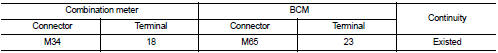
2. Check continuity between combination meter harness connector and BCM harness connector.
3. Check continuity between combination meter harness connector and ground.

Is the inspection result normal? YES >> Replace combination meter. Refer to MWI-69, "Removal and Installation".
NO >> Repair or replace harness.
 Horn function
Component Function Check
1.CHECK FUNCTION 1
1. Disconnect vehicle security horn relay.
2. Perform “VEHICLE SECURITY HORN” in “ACTIVE TEST” mode of “THEFT ALM” of “BCM”
using CONSULT-
III.
3. Ch ...

Other materials:
Malfunction indicator
Component Function Check
1.CHECK MI FUNCTION
1. Turn ignition switch ON.
2. Make sure that MI lights up.
Is the inspection result normal?
YES >> INSPECTION END
NO >> Go to EC-789, "Diagnosis Procedure".
Diagnosis Procedure
1.CHECK DTC
Check that DTC U1001 is not disp ...
F.M.V.S.S./C.M.V.S.S. certification label
The Federal/Canadian Motor Vehicle Safety Standards (F.M.V.S.S./C.M.V.S.S.) certification
label is affixed as shown. This label contains valuable vehicle information, such
as: Gross Vehicle Weight Ratings (GVWR), Gross Axle Weight Rating (GAWR), month
and year of manufacture, Vehicle Identif ...
PC415 communication circuit
Description
CAN (Controller Area Network) is a serial communication line for real time
application. It is an on-vehicle multiplex
communication line with high data communication speed and excellent error
detection ability. Many electronic
control units are equipped onto a vehicle, and each co ...