Nissan Juke Service and Repair Manual : Remote keyless entry receiver
Component Function Check
1.CHECK FUNCTION
1. Select “INTELLIGENT KEY” of “BCM” using CONSULT-III.
2. Select “RKE OPE COUN1” in “DATA MONITOR” mode.
3. Check that the function operates normally according to the following conditions.

Is the inspection result normal? YES >> Remote keyless entry receiver is OK.
NO >> Refer to DLK-95, "Diagnosis Procedure".
Diagnosis Procedure
1.CHECK REMOTE KEYLESS ENTRY RECEIVER GROUND CIRCUIT
1. Turn ignition switch OFF.
2. Disconnect BCM connector and remote keyless entry receiver connector.
3. Check continuity between BCM harness connector and remote keyless entry receiver harness connector.

4. Check continuity between BCM harness connector and ground.
Is the inspection result normal? YES >> GO TO 2.
NO >> Repair or replace harness.
2.CHECK REMOTE KEYLESS ENTRY RECEIVER POWER SUPPLY
1. Reconnect BCM connector.
2. Check voltage between remote keyless entry receiver harness connector and ground.

Is the inspection result normal? YES >> GO TO 4.
NO >> GO TO 3.
3.CHECK REMOTE KEYLESS ENTRY RECEIVER CIRCUIT 1
1. Disconnect BCM connector 2. Check continuity between BCM harness connector and remote keyless entry receiver harness connector.

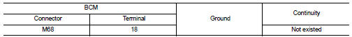
3. Check continuity between BCM harness connector and ground.

Is the inspection result normal? YES >> Replace BCM. Refer to BCS-93, "Removal and Installation".
NO >> Repair or replace harness.
4.CHECK REMOTE KEYLESS ENTRY RECEIVER OUTPUT SIGNAL
1. Reconnect remote keyless entry receiver connector.
2. Check signal between remote keyless entry receiver harness connector and ground using oscilloscope.

Is the inspection result normal? YES >> GO TO 5.
NO >> Replace remote keyless entry receiver.
5.CHECK REMOTE KEYLESS ENTRY RECEIVER CIRCUIT 2
1. Disconnect BCM connector and remote keyless entry receiver connector.
2. Check continuity between BCM harness connector and remote keyless entry receiver harness connector.

3. Check continuity between BCM harness connector and ground.

Is the inspection result normal? YES >> GO TO 6.
NO >> Repair or replace harness.
6.CHECK REMOTE KEYLESS ENTRY RECEIVER RSSI OUTPUT SIGNAL
1. Reconnect BCM and remote keyless entry receiver connector.
2. Check signal between remote keyless entry receiver harness connector and ground using oscilloscope.

Is the inspection result normal? YES >> GO TO 7.
NO >> Replace remote keyless entry receiver.
7.CHECK REMOTE KEYLESS ENTRY RECEIVER RSSI CIRCUIT
1. Disconnect BCM and remote keyless entry receiver connector.
2. Check continuity between BCM harness connector and remote keyless entry receiver harness connector.

3. Check continuity between BCM harness connector and ground.

Is the inspection result normal? YES >> Replace BCM. Refer to BCS-93, "Removal and Installation".
NO >> Repair or replace harness.
 Key warning lamp
Component Function Check
1.CHECK FUNCTION
1. Select “INTELLIGENT KEY” of “BCM” using CONSULT-III.
2. Select “INDICATOR” in “ACTIVE TEST” mode.
3. Check that the function operates normally accordin ...
 Shift P warning lamp
Component Function Check
1.CHECK FUNCTION
1. Select “INTELLIGENT KEY” of “BCM” using CONSULT-III.
2. Select “LCD” in “ACTIVE TEST” mode.
3. Check that the function operates normally according to t ...
Other materials:
Buzzer (combination meter)
Component Function Check
1.CHECK FUNCTION
1. Select “INTELLIGENT KEY” of “BCM” using CONSULT-III.
2. Select “INSIDE BUZZER” in “ACTIVE TEST” mode.
3. Check that the function operates normally according to the following
conditions.
Is the inspection result normal?
Yes >> Buzzer (combi ...
Precautions on supplemental restraint system
This Supplemental Restraint System (SRS) section contains important information
concerning the following systems:
• Driver and passenger supplemental frontimpact air bag (NISSAN Advanced Air Bag
System)
• Front seat-mounted side-impact supplemental air bag
• Roof-mounted curtain side-impact s ...
Car phone or CB radio
When installing a car phone or a CB radio in your vehicle, be sure to observe
the following precautions, otherwise the new equipment may adversely affect the
electronic control modules and electronic control system harness.
WARNING
• A cellular phone should not be used for any purpose wh ...