Nissan Juke Service and Repair Manual : Rear window defogger switch
With auto A/C
WITH AUTO A/C : Description
• The rear window defogger is operated by turning the rear window defogger switch ON.
• The indicator lamp in the rear window defogger switch illuminates when the rear window defogger is operating.
WITH AUTO A/C : Component Function Check
1.CHECK REAR WINDOW DEFOGGER SWITCH FUNCTION
Check that the indicator lamp of rear window defogger illuminates when rear window defogger switch ON.
Is the inspection result normal? YES >> Rear window defogger switch function is OK.
NO >> Refer to DEF-26, "WITH AUTO A/C : Diagnosis Procedure"
WITH AUTO A/C : Diagnosis Procedure
1.CHECK MULTI DISPLAY UNIT (REAR WINDOW DEFOGGER SWITCH)
Does multi display unit (rear window defogger switch) operate normally? • Auto A/C (4WD models). Refer to HAC-29, "Description".
• Auto A/C (2WD models). Refer to HAC-121, "Description".
Is the inspection result normal? YES >> INSPECTION END NO >> Replace multi display unit (rear window defogger switch).
Without auto A/C
WITHOUT AUTO A/C : Description
• The rear window defogger is operated by turning the rear window defogger switch ON.
• The indicator lamp in the rear window defogger switch illuminates when the rear window defogger is operating.
WITHOUT AUTO A/C : Component Function Check
1.CHECK FUNCTION
Check (REAR DEF SW) in BCM “DATA MONITOR”mode using CONSULT-III when rear window defogger switch is ON.
Is the inspection result normal? YES >> Rear window defogger switch function is OK.
NO >> Refer to DEF-26, "WITHOUT AUTO A/C : Diagnosis Procedure"
WITHOUT AUTO A/C : Diagnosis Procedure
1.CHECK BCM OUTPUT SIGNAL
1. Turn ignition switch OFF.
2. Disconnect A/C control connector.
3. Check voltage between A/C control harness connector and ground.

Is the inspection result normal? YES >> GO TO 3.
NO >> GO TO 2.
2.CHECK REAR WINDOW DEFOGGER SWITCH CIRCUIT
1. Disconnect BCM connector.
2. Check continuity between BCM harness connector and A/C control harness connector.

3. Check continuity between BCM harness connector and ground.

Is the inspection result normal? YES >> Replace BCM. Refer to BCS-93, "Removal and Installation" (With Intelligent Key system) or BCS- 161, "Removal and Installation" (Without Intelligent Key system).
NO >> Repair or replace harness.
3.CHECK GROUND CIRCUIT
Check continuity between A/C control harness connector and ground.

Is the inspection result normal? YES >> GO TO 4.
NO >> Repair or replace harness.
4.CHECK REAR WINDOW DEFOGGER SWITCH
Refer to DEF-27, "WITHOUT AUTO A/C : Component Inspection".
Is the inspection result normal? YES >> GO TO 5.
NO >> Replace A/C control. Refer to HAC-239, "Removal and Installation" (4WD models) or HAC-304, "Removal and Installation" (2WD models).
5.CHECK INTERMITTENT INCIDENT
Refer to GI-42, "Intermittent Incident".
Is the inspection result normal? >> INSPECTION END
WITHOUT AUTO A/C : Component Inspection
1.CHECK REAR WINDOW DEFOGGER SWITCH
1. Turn ignition switch OFF.
2. Disconnect A/C control connector.
3. Check continuity between A/C control terminals.

Is the inspection result normal? YES >> INSPECTION END
NO >> Replace A/C control. Refer to HAC-239, "Removal and Installation" (4WD models) or HAC-304, "Removal and Installation" (2WD models).
Without A/C
WITHOUT A/C : Description
• The rear window defogger is operated by turning the rear window defogger switch ON.
• The indicator lamp in the rear window defogger switch illuminates when the rear window defogger is operating.
WITHOUT A/C : Component Function Check
1.CHECK FUNCTION
Check (REAR DEF SW) in BCM “DATA MONITOR”mode using CONSULT-III when rear window defogger switch is ON.
Is the inspection result normal? YES >> Rear window defogger switch function is OK.
NO >> Refer to DEF-28, "WITHOUT A/C : Diagnosis Procedure"
WITHOUT A/C : Diagnosis Procedure
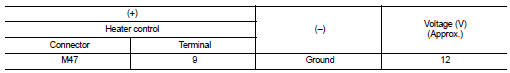
1.CHECK BCM OUTPUT SIGNAL
1. Turn ignition switch OFF.
2. Disconnect heater control connector.
3. Check voltage between heater control harness connector and groun
Is the inspection result normal? YES >> GO TO 3.
NO >> GO TO 2.
2.CHECK REAR WINDOW DEFOGGER SWITCH CIRCUIT
1. Disconnect BCM connector.
2. Check continuity between BCM harness connector and heater control harness connector.

3. Check continuity between BCM harness connector and groun

Is the inspection result normal?
YES >> Replace BCM. Refer to BCS-161, "Removal and Installation".
NO >> Repair or replace harness.
3.CHECK GROUND CIRCUIT
Check continuity between heater control harness connector and ground.

Is the inspection result normal? YES >> GO TO 4.
NO >> Repair or replace harness.
4.CHECK REAR WINDOW DEFOGGER SWITCH
Refer to DEF-29, "WITHOUT A/C : Component Inspection".
Is the inspection result normal? YES >> GO TO 5.
NO >> Replace heater control. Refer to HAC-331, "Removal and Installation".
5.CHECK INTERMITTENT INCIDENT
Refer to GI-42, "Intermittent Incident".
Is the inspection result normal? >> INSPECTION END
WITHOUT A/C : Component Inspection
1.CHECK REAR WINDOW DEFOGGER SWITCH
1. Turn ignition switch OFF.
2. Disconnect heater control connector.
3. Check continuity between heater control terminals.

Is the inspection result normal? YES >> INSPECTION END
NO >> Replace heater control. Refer to HAC-331, "Removal and Installation".

 Rear window defogger relay
Description
The rear window defogger is operated by turning the rear window defogger
switch ON.
Component Function Check
1.CHECK FUNCTION
1. Perform IPDM E/R Active Test (“REAR DEFOGGER”) using ...
Other materials:
P0697 sensor power supply
DTC Logic
DTC DETECTION LOGIC
Diagnosis Procedure
1.CHECK GROUND CONNECTION
1. Turn ignition switch OFF and wait at least 4 minutes.
2. Check ground connection E38. Refer to Ground Inspection in GI-44, "Circuit
Inspection".
Is the inspection result normal?
YES >> GO TO 2 ...
Engine idle speed too low or unstable
Description
CHART 6: ENGINE IDLE SPEED TOO LOW OR UNSTABLE
Diagnosis Procedure
1.CHECK FUEL
Check that the fuel reservoir is correctly filled and with the right fuel.
>> GO TO 2.
2.CHECK ECM POWER SUPPLY AND GROUND CIRCUIT
Check ECM power supply and ground circuit. Refer to EC-885, ...
Steering wheel turning force is heavy or light
Description
Steering wheel turning force is heavy or light.
Diagnosis Procedure
1.CHECK THE ILLUMINATION OF THE EPS WARNING LAMP
Check that the EPS warning lamp turns ON when ignition switch turns ON. Then,
EPS warning lamp turns
OFF after the engine is started.
Is the inspection result no ...