Nissan Juke Service and Repair Manual : Power supply and ground circuit
Diagnosis Procedure
1.CHECK ABS ACTUATOR AND ELECTRIC UNIT (CONTROL UNIT) IGNITION POWER SUPPLY
1. Turn the ignition switch OFF.
2. Disconnect ABS actuator and electric unit (control unit) harness connector.
3. Check voltage between ABS actuator and electric unit (control unit) harness connector and ground.

4. Turn the ignition switch ON
CAUTION:
Never start engine
.
5. Check voltage between ABS actuator and electric unit (control unit) harness connector and ground.

Is the inspection result normal? YES >> GO TO 3.
NO >> GO TO 2.
2.CHECK ABS ACTUATOR AND ELECTRIC UNIT (CONTROL UNIT) IGNITION POWER SUPPLY CIRCUIT
1. Turn the ignition switch OFF.
2. Check 10 A fuse (#57).
3. Disconnect IPDM E/R harness connector.
4. Check continuity between ABS actuator and electric unit (control unit) harness connector and IPDM E/R harness connector

5. Check for continuity between ABS actuator and electric unit (control unit) harness connector and the ground.

Is the inspection result normal? YES >> Perform trouble diagnosis for ignition power supply. Refer to PG-15, "Wiring Diagram - IGNITION POWER SUPPLY -".
NO >> Repair or replace error-detected parts.
3.CHECK MOTOR AND MOTOR RELAY POWER SUPPLY
1. Turn the ignition switch OFF.
2. Check voltage between ABS actuator and electric unit (control unit) harness connector and ground.

3. Turn the ignition switch ON.
CAUTION:
Never start engine.
4. Check voltage between ABS actuator and electric unit (control unit) harness connector and ground.

Is the inspection result normal? YES >> GO TO 5.
NO >> GO TO 4.
4.CHECK MOTOR AND MOTOR RELAY POWER SUPPLY CIRCUIT
1. Turn the ignition switch OFF.
2. Check 30 A fusible link (K).
3. Check continuity and short circuit between ABS actuator and electric unit (control unit) harness connector terminal (1) and 30 A fusible link (K).
Is the inspection result normal? YES >> Perform trouble diagnosis for battery power supply. Refer to PG-10, "Wiring Diagram - BATTERY POWER SUPPLY -".
NO >> Repair or replace error-detected parts.
5.CHECK ACTUATOR RELAY, ABS IN VALVE, ABS OUT VALVE POWER SUPPLY
1. Turn the ignition switch OFF.
2. Check voltage between ABS actuator and electric unit (control unit) harness connector and ground.

3. Turn the ignition switch ON
CAUTION:
Never start engine.
4. Check voltage between ABS actuator and electric unit (control unit) harness connector and ground.
Is the inspection result normal? YES >> GO TO 7.
NO >> GO TO 6.
6.CHECK ACTUATOR RELAY, ABS IN VALVE, ABS OUT VALVE POWER SUPPLY CIRCUIT
1. Turn the ignition switch OFF.
2. Check 50 A fusible link (I).
3. Check continuity and short circuit between ABS actuator and electric unit (control unit) harness connector terminal (2) and 50 A fusible link (I).
Is the inspection result normal? YES >> Perform trouble diagnosis for battery power supply. Refer to PG-10, "Wiring Diagram - BATTERY POWER SUPPLY -".
NO >> Repair or replace error-detected parts.
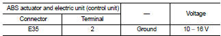
7.CHECK ABS ACTUATOR AND ELECTRIC UNIT (CONTROL UNIT) GROUND CIRCUIT
Check for continuity between ABS actuator and electric unit (control unit) harness connector and the ground.

Is the inspection result normal? YES >> GO TO 8.
NO >> Repair or replace error-detected parts.
8.CHECK TERMINAL
• Check ABS actuator and electric unit (control unit) pin terminals for damage or loose connection with harness connector.
• Check IPDM E/R pin terminals for damage or loose connection with harness connector.
Is the inspection result normal? YES >> INSPECTION END
NO >> Repair or replace error-detected parts.
 U1010 control unit (can)
Description
CAN (Controller Area Network) is a serial communication line for real time
application. It is an on-vehicle multiplex
communication line with high data communication speed and excellen ...
 Parking brake switch
Component Function Check
1.CHECK PARKING BRAKE SWITCH OPERATION
Operate the parking brake lever. Then check that the brake warning lamp in
the combination meter turns ON/
OFF correctly.
Is the ...
Other materials:
Turbocharger (If Equipped)
The turbocharger turbine revolves at extremely high speeds and
becomes very hot. Therefore, it is essential to maintain a clean supply
of oil flowing through the turbocharger and to follow all required
maintenance instructions and operating procedures.
• Always use the recommended oil. Follow ...
S mode switch
Component Function Check
1.CHECK S MODE INDICATOR FUNCTION
Check S mode indicator turns ON for approx. 2 seconds when ignition switch
turns ON.
Is the inspection results normal?
YES >> GO TO 2.
NO >> Go to TM-469, "Diagnosis Procedure".
2.CHECK S MODE SWITCH FUNCT ...
P0607 ECM
DTC Logic
DTC DETECTION LOGIC
DTC CONFIRMATION PROCEDURE
1.PERFORM DTC CONFIRMATION PROCEDURE
1. Turn ignition switch ON.
2. Check DTC.
Is DTC detected?
YES >> Proceed to EC-304, "Diagnosis Procedure".
NO >> INSPECTION END
Diagnosis Procedur
1.INSPECTION START
...