Nissan Juke Service and Repair Manual : Power supply and ground circuit
Diagnosis Procedure
1.CHECK 4WD CONTROL MODULE POWER SUPPLY (1)
1. Turn the ignition switch OFF.
2. Disconnect 4WD control module harness connector.
3. Check the voltage between 4WD control module harness connector and ground.

4. Turn the ignition switch ON.
CAUTION:
Never start the engine.
5. Check the voltage between 4WD control module harness connector and ground.

Is the inspection result normal? YES >> GO TO 3.
NO >> GO TO 2.
2.CHECK 4WD CONTROL MODULE POWER SUPPLY (2)
1. Turn the ignition switch OFF.
2. Check the 10A fuse (#33).
3. Check the harness for open or short between 4WD control module harness connector No.1 terminal and 10A (#33).
Is the inspection result normal? YES >> Perform the trouble diagnosis for power supply circuit. Refer to PG-10, "Wiring Diagram - BATTERY POWER SUPPLY -".
NO >> Repair or replace error-detected parts.
3.CHECK 4WD CONTROL MODULE POWER SUPPLY (3)
1. Turn the ignition switch OFF.
2. Check the voltage between 4WD control module harness connector and ground.
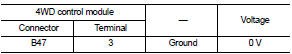
3. Turn the ignition switch ON.
CAUTION:
Never start the engine.
4. Check the voltage between 4WD control module harness connector and ground.

Is the inspection result normal? YES >> GO TO 5.
NO >> GO TO 4.
4.CHECK 4WD CONTROL MODULE POWER SUPPLY (4)
1. Turn the ignition switch OFF.
2. Check the 10A fuse (#3).
3. Check the harness for open or short between 4WD control module harness connector No.3 terminal and 10A (#3).
Is the inspection result normal? YES >> Perform the trouble diagnosis for ignition power supply circuit. Refer to PG-15, "Wiring Diagram - IGNITION POWER SUPPLY -".
NO >> Repair or replace error-detected parts.
5.CHECK 4WD SOLENOID POWER SUPPLY (1)
1. Turn the ignition switch OFF.
2. Disconnect 4WD control module harness connector.
3. Check the voltage between 4WD control module harness connector and ground.

4. Turn the ignition switch OFF to ON.
CAUTION:
Never start the engine.
5. Check the voltage between 4WD control module harness connector and ground.

Is the inspection result normal? YES >> GO TO 7.
NO >> GO TO 6.
6.CHECK 4WD SOLENOID POWER SUPPLY (2)
1. Turn the ignition switch OFF.
2. Check the 10A fuse (#12).
3. Check the harness for open or short between 4WD control module harness connector No.12 and the 10A fuse (#12).
Is the inspection result normal? YES >> Perform the trouble the diagnosis for power supply circuit. Refer to PG-10, "Wiring Diagram - BATTERY POWER SUPPLY -".
NO >> Repair or replace error-detected parts.
7.CHECK 4WD CONTROL MODULE GROUND
1. Turn the ignition switch OFF.
2. Check the continuity between 4WD control module harness connector and ground.

Is the inspection result normal? YES >> INSPECTION END
NO >> Repair or replace error-detected parts.
 U1010 control unit (CAN)
Description
CAN (Controller Area Network) is a serial communication line for real time
application. It is an on-vehicle multiplex
communication line with high data communication speed and excellen ...
 4WD warning lamp
Component Function Check
1.CHECK 4WD WARNING LAMP FUNCTION
1. Turn the ignition switch ON.
2. Check that 4WD warning lamp turns on.
Is the inspection result normal?
YES >> INSPECTION END
...
Other materials:
Component parts
Component Parts Location
1. A/C auto amp.
Refer to HAC-12, "Component Parts
Location".
2. ABS actuator and electric unit (control
unit)
Refer to BRC-9, "Component Parts
Location" (without ESP) or BRC-97,
"Component Parts Location" (with
ESP).
3. ECM
Refer t ...
Heated seat switch
Exploded View
1. Heated seat swich
2. Switch bracket
3. Console switch finisher
Removal and Installation
REMOVAL
CAUTION:
When removing and installing, use shop cloths to protect from damage.
1. Remove the console switch finisher. Refer to IP-23, "Removal and
Installation".
...
Interior room lamp power supply circuit
Description
Provides the interior room lamp power supply. Also cuts the power supply when
the interior room lamp battery
saver activating.
Component Function Check
1.CHECK INTERIOR ROOM LAMP POWER SUPPLY FUNCTION
CONSULT-III ACTIVE TEST
1. Turn ignition switch ON.
2. Turn each interior room ...