Nissan Juke Service and Repair Manual : P1805 brake switch
DTC Logic
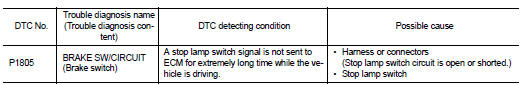
DTC DETECTION LOGIC
DTC CONFIRMATION PROCEDURE
1.PERFORM DTC CONFIRMATION PROCEDURE
1. Turn ignition switch ON.
2. Fully depress the brake pedal for at least 5 seconds.
3. Erase the DTC.
4. Check 1st trip DTC.
Is 1st trip DTC detected? YES >> Proceed to EC-374, "Diagnosis Procedure".
NO >> INSPECTION END
Diagnosis Procedure
1.CHECK STOP LAMP SWITCH POWER SUPPLY CIRCUIT
1. Turn ignition switch OFF.
2. Disconnect stop lamp switch harness connector.
3. Check the voltage between stop lamp switch harness connector and ground.

*1: CVT models
*2: LHD with M/T models
*3: RHD with M/T models
Is the inspection result normal? YES >> GO TO 2.
NO >> Perform the trouble diagnosis for power supply circuit.
2.CHECK STOP LAMP SWITCH INPUT SIGNAL CIRCUIT
1. Disconnect ECM harness connector.
2. Check the continuity between stop lamp switch harness connector and ECM harness connec

*1: CVT models
*2: LHD with M/T models
*3: RHD with M/T models
3. Also check harness for short to ground and to power.
Is the inspection result normal? YES >> GO TO 3.
NO >> Repair or replace error-detected parts.
3.CHECK STOP LAMP SWITCH
Check the stop lamp switch. Refer to EC-375, "Component Inspection (Stop Lamp Switch)".
Is the inspection result normal? YES >> Check intermittent incident. Refer to GI-42, "Intermittent Incident".
NO >> Replace stop lamp switch. Refer to BR-20, "Exploded View" (LHD) or BR-88, "Exploded View" (RHD).
Component Inspection (Stop Lamp Switch)
1.CHECK STOP LAMP SWITCH-I
1. Turn ignition switch OFF.
2. Disconnect stop lamp switch harness connector.
3. Check the continuity between stop lamp switch terminals as per the following conditions.

Is the inspection result normal? YES >> INSPECTION END
NO >> GO TO 2.
2.CHECK STOP LAMP SWITCH-II
1. Adjust stop lamp switch installation. Refer to BR-9, "Inspection and Adjustment" (LHD) or BR-77, "Inspection and Adjustment" (RHD).
2. Check the continuity between stop lamp switch terminals as per the following conditions.

Is the inspection result normal? YES >> INSPECTION END
NO >> Replace stop lamp switch. Refer to BR-20, "Exploded View" (LHD) or BR-88, "Exploded View" (RHD).
 P1652 starter motor system COMM
Description
ECM controls ON/OFF state of the starter relay, according to the engine and
vehicle condition. Models with no
Intelligent Key System transmit a control signal directly to IPDM E/R. On ...
 P2100, P2103 throttle control motor relay
DTC Logic
DTC CONFIRMATION PROCEDURE
1.PRECONDITIONING
If DTC Confirmation Procedure has been previously conducted, always perform
the following procedure
before conducting the next test.
1. ...
Other materials:
Refrigeration system symptoms
Trouble Diagnosis For Unusual Pressure
Diagnose using a manifold gauge whenever system’s high and/or low side
pressure(s) is/are unusual. The
marker above the gauge scale in the following tables indicates the standard
(usual) pressure range. Refer to
above table (Ambient air temperature-to-op ...
Service data and specifications (SDS)
Wheel Bearing
Drive Shaft
M/T
*: For measuring position, refer to FAX-54, "WHEEL SIDE : Disassembly and
Assembly" (Wheel side), FAX-
56, "TRANSAXLE SIDE : Disassembly and Assembly" (Transaxle side).
CVT
*: For measuring position, refer to FAX-54, "WHEEL SIDE ...
Vehicle speed sensing auto lock operation does not operate
Diagnosis Procedure
1.CHECK “AUTOMATIC LOCK/UNLOCK SELECT” SETTING IN “WORK SUPPORT”
1. Select “DOOR LOCK” of “BCM” using CONSULT-III.
2. Select “AUTOMATIC LOCK/UNLOCK SELECT” in “WORK SUPPORT” mode.
3. Check “AUTOMATIC LOCK/UNLOCK SELECT” in “WORK SUPPORT”.
Refer to DLK-217, "DOOR LOCK ...
