Nissan Juke Service and Repair Manual : P1777 step motor
DTC Logic
DTC DETECTION LOGIC

DTC CONFIRMATION PROCEDURE
CAUTION:
Always drive vehicle at a safe speed.
NOTE:
If “DTC CONFIRMATION PROCEDURE” has been previously performed, always turn ignition switch OFF and wait at least 10 seconds before performing the next test.
After the repair, perform the following procedure to confirm the malfunction is eliminated.
1.CHECK DTC DETECTION
 With CONSULT-III
1. Turn ignition switch ON.
2. Drive vehicle for at least 5 consecutive seconds.
3. Select “Self Diagnostic Results” in “TRANSMISSION”.
 With GST
Follow the procedure “With CONSULT-III”.
Is “P1777” detected? YES >> Go to TM-250, "Diagnosis Procedure".
NO >> Check intermittent incident. Refer to GI-42, "Intermittent Incident".
Diagnosis Procedure
1.CHECK INPUT SIGNALS
With CONSULT-III
1. Start engine.
2. Select “DATA MONITOR”.
3. Start vehicle and read out the value of “STM STEP”, “SMCOIL A”, “SMCOIL B”, “SMCOIL C”, and “SMCOIL D”.

Is the inspection result normal? YES >> GO TO 4.
NO >> GO TO 2.
2.CHECK HARNESS BETWEEN TCM AND STEP MOTOR
1. Turn ignition switch OFF.
2. Disconnect CVT unit harness connector and TCM connector.
3. Check continuity between TCM connector terminals and CVT unit harness connector terminals.

4. If OK, check harness for short to ground and short to power.
5. If OK, check continuity between body ground and transaxle assembly.
6. Reinstall any part removed.
Is the inspection result normal? YES >> GO TO 3.
NO >> Repair or replace damaged parts.
3.CHECK STEP MOTOR
Check step motor. Refer to TM-251, "Component Inspection".
Is the inspection result normal? YES >> GO TO 4.
NO >> Repair or replace damaged parts.
4.CHECK TCM
Check TCM input/output signals. Refer to TM-164, "Reference Value".
Is the inspection result normal? YES >> Check intermittent incident. Refer to GI-42, "Intermittent Incident".
NO >> Replace the TCM. Refer to TM-280, "Removal and Installation".
Component Inspection
STEP MOTOR
1.STEP MOTOR
1. Turn ignition switch OFF.
2. Disconnect CVT unit harness connector.
3. Check resistance between CVT unit harness connector terminals and ground.
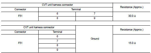
Is the inspection result normal? YES >> INSPECTION END
NO >> Replace the transaxle assembly. Refer to TM-301, "Removal and Installation".
 P1745 line pressure control
Description
The line pressure solenoid valve regulates the oil pump discharge pressure to
suit the driving condition in
response to a signal sent from the TCM.
DTC Logic
DTC DETECTION LOGIC
D ...
 P1778 step motor
Description
• The step motor's 4 aspects of ON/OFF change according to the signal from
TCM. As a result, the flow of line
pressure to primary pulley is changed and pulley ratio is controlled.
• T ...
Other materials:
Exploded View
1. O-ring
2. Oil pan (upper)
3. Oil level gauge guide
4. O-ring
5. Oil level gauge
6. Oil pump drive chain
7. Crankshaft sprocket
8. Oil pump sprocket
9. Oil pump chain tensioner
10. Oil pump
11. Drain plug
12. Drain plug washer
13. Oil pan (lower)
14. Oil filter
15. Connec ...
Precaution
Service Notice or Precautions for Road Wheel
• Genuine NISSAN aluminum wheel is designed for each type of vehicle. Use it
on the specified vehicle only.
• Use Genuine NISSAN parts for the wheel nuts.
• Always use them after adjusting the wheel balance. For the balance weights,
use Genuine NIS ...
P173C 2GR incorrect ratio
DTC Logic
DTC DETECTION LOGIC
DTC CONFIRMATION PROCEDURE
CAUTION:
• Be sure to perform “TM-447, "Diagnosis Procedure"” and then perform “DTC
CONFIRMATION PROCEDURE”.
• Never perform "DTC CONFIRMATION PROCEDURE" before the repairs. Doing so may
result in a secondary
ma ...