Nissan Juke Service and Repair Manual : P159B G sensor
For M/T models : DTC Logic
DTC DETECTION LOGIC

DTC CONFIRMATION PROCEDURE
1.PRECONDITIONING
If DTC Confirmation Procedure has been previously conducted, always perform the following procedure before conducting the next test.
1. Turn ignition switch OFF and wait at least 10 seconds.
2. Turn ignition switch ON.
3. Turn ignition switch OFF and wait at least 10 seconds.
TEST CONDITION:
Before performing the following procedure, confirm that battery voltage is more
than 11 V at idle.
> GO TO 2.
2.PERFORM DTC CONFIRMATION PROCEDURE
1. Start engine.
2. Drive the vehicle for at least 5 seconds at 35 km/h (22 MPH) or more.
3. Stop the vehicle and let it idle for at least 5 seconds.
NOTE
:
• Depress the brake pedal to bring the vehicle to a full stop.
• Never depress the accelerator pedal while the vehicle is stoppe
4. Repeat Step 2 and Step 3 thirteen times.
5. Check 1st trip DTC.
Is 1st trip DTC detected? YES >> Proceed to EC-361, "FOR M/T MODELS : Diagnosis Procedure".
NO >> INSPECTION END
For M/T models : Diagnosis Pr
1.PERFORM CALIBRATION OF G SENSOR
Perform calibration of G sensor. Refer to EC-138, "Work Procedure".
>> GO TO 2.
2.PERFORM DTC CONFIRMATION PROCEDURE
Perform DTC Confirmation Procedure. Refer to EC-360, "FOR M/T MODELS : DTC Logic".
Is 1st trip DTC detected? YES >> GO TO 3.
NO >> INSPECTION END
3.CHECK G SENSOR FITTING CONDITION
Check G sensor fitting condition.
Is the inspection result normal? YES >> GO TO 4.
NO >> 1. Adjust parts fitting condition.
2. Perform calibration of G sensor. Refer to EC-138, "Work Procedure".
4.CHECK G SENSOR POWER SUPPLY CIRCUIT-I
1. Turn ignition switch OFF.
2. Disconnect G sensor harness connector.
3. Turn ignition switch ON.
4. Check the voltage between G sensor harness connector terminals.

Is the inspection result normal? YES >> GO TO 5.
NO >> GO TO 7.
5.CHECK G SENSOR SIGNAL CIRCUIT
1. Turn ignition switch OFF.
2. Disconnect ECM harness connector.
3. Check the continuity between G sensor harness connector and ECM harness connector.

4. Also check harness for short to ground and short to power.
Is the inspection result normal? YES >> GO TO 6.
NO >> Repair or replace error-detected parts.
6.CHECK G SENSOR
Check G sensor. Refer to EC-363, "FOR M/T MODELS : Component Inspection".
Is the inspection result normal? YES >> Check intermittent incident. Refer to GI-42, "Intermittent Incident".
NO >> 1. Replace G sensor. Refer to TM-282, "Exploded View".
2. Perform calibration of G sensor. Refer to EC-138, "Work Procedure".
7.CHECK G SENSOR POWER SUPPLY CIRCUIT-II
Check the voltage between G sensor harness connector terminal and ground.

Is the inspection result normal? YES >> GO TO 8.
NO >> GO TO 10.
8.CHECK G SENSOR GROUND CIRCUIT
1. Turn ignition switch OFF.
2. Disconnect ECM harness connector.
3. Check the continuity between G sensor harness connector and ECM harness connector.

Is the inspection result normal? YES >> GO TO 9.
NO >> Repair or replace error-detected parts.
9.CHECK ECM GROUND CIRCUIT
Check the continuity between ECM harness connector and ground.
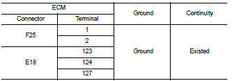
Is the inspection result normal? YES >> Check intermittent incident. Refer to GI-42, "Intermittent Incident".
NO >> Repair or replace error-detected parts.
10.CHECK SENSOR POWER SUPPLY CIRCUIT
1. Turn ignition switch OFF.
2. Disconnect ECM harness connectors and each sensor harness connectors 3. Check harness connector for short to power and short to ground, between the following terminals.

*1: CVT models
*2: RHD with M/T models
Is the inspection result normal? YES >> Perform the trouble diagnosis for power supply circuit.
NO >> Repair or replace error-detected parts.
For M/T models : Component Inspection
1.CHECK G SENSOR
 With CONSULT-III
1. Remove G sensor. Refer to TM-282, "Exploded View".
2. Reconnect all harness connectors disconnected.
3. Place the G sensor on a flat table.
4. Turn ignition switch ON.
5. Select “G SENSOR” in “DATA MONITOR” mode of “ENGINE” using CONSULT-III to check indications according to the following conditions:
 : Direction of gravitational
force


*: Check that voltage rises as the G sensor measurement condition changes in the order of (A), (B), and (C).
 Without CONSULT-III
1. Remove G sensor. Refer to TM-282, "Exploded View".
2. Reconnect all harness connectors disconnected.
3. Place the G sensor on a flat table.
4. Turn ignition switch ON.5. Check the voltage between ECM harness connector terminal and ground.
5. Check the voltage between ECM harness connector terminal and ground.
: Direction of gravitational
force

*: Check that voltage rises as the G sensor measurement condition changes in the order of (A), (B), and (C).
Is the inspection result normal? YES >> INSPECTION END
NO >> Replace G sensor. Refer to TM-282, "Exploded View".
Except for M/T models : Description
ECM receives a G sensor signal from TCM via CAN communication to switch combustion for the direct injection gasoline system. For the direct injection gasoline system, refer to EC-48, "DIRECT INJECTION GASOLINE SYSTEM : System Description".
Except for M/T models : DTC Logic
DTC DETECTION LOGIC
NOTE
:
• If DTC P159B is displayed with DTC UXXX, first perform the trouble diagnosis
for DTC UXXXX. Refer to EC-
108, "DTC Index".
• If DTC P159B is displayed with DTC P0607, first perform the trouble diagnosis for DTC P0607. Refer to EC- 304, "DTC Logic".

DTC CONFIRMATION PROCEDURE
1.PRECONDITIONING
If DTC Confirmation Procedure has been previously conducted, always perform the following procedure before conducting the next test.
1. Turn ignition switch OFF and wait at least 10 seconds.
2. Turn ignition switch ON.
3. Turn ignition switch OFF and wait at least 10 seconds.
TEST CONDITION:
Before performing the following procedure, confirm that battery voltage is more
than 11 V at idle.
>> GO TO 2.
2.PERFORM DTC CONFIRMATION PROCEDURE
1. Start engine.
2. Drive the vehicle at least 5 seconds at 35 km/h (22 MPH) or more.
3. Stop the vehicle and let it idle at least 5 seconds.
NOTE
:
• Depress the brake pedal to bring the vehicle to a full stop.
• Never depress the accelerator pedal while the vehicle is stopped.
4. Repeat Step 2 and Step 3 thirteen times.
5. Check 1st trip DTC.
Is 1st trip DTC detected? YES >> Proceed to EC-365, "EXCEPT FOR M/T MODELS : Diagnosis Procedure".
NO >> INSPECTION END
Except for M/T models : Diagnosis Procedure
1.CHECK DTC WITH TCM
 With CONSULT-III
Check DTC with TCM. Refer to TM-159, "CONSULT-III Function (TRANSMISSION)".
Is the inspection result normal? YES >> GO TO 2.
NO >> Perform Diagnosis Procedure corresponding to DTC indicated.
2.PERFORM CALIBRATION OF G SENSOR
Perform calibration of G sensor. Refer to EC-138, "Work Procedure".
>> GO TO 3.
3.PERFORM DTC CONFIRMATION PROCEDURE
Perform DTC Confirmation Procedure. Refer to EC-364, "EXCEPT FOR M/T MODELS : DTC Logic".
Is 1st trip DTC detected? YES >> GO TO 4.
NO >> INSPECTION END
4.CHECK G SENSOR FITTING CONDITION
Check G sensor fitting condition.
Is the inspection result normal? YES >> GO TO 5.
NO >> 1. Adjust parts fitting condition.
2. Perform calibration of G sensor. Refer to TM-182, "Procedure".
5.PERFORM DIAGNOSIS PROCEDURE OF G SENSOR
Perform Diagnosis procedure of G sensor. Refer to TM-236, "Diagnosis Procedure".
Is the inspection result normal? YES >> INSPECTION END
NO >> Check intermittent incident. Refer to GI-42, "Intermittent Incident".
 Except for M/T models
Except for M/T models : Description
ECM receives a G sensor signal from TCM via CAN communication to switch
combustion for the direct injection
gasoline system. For the direct injection gasoline s ...
 P1650 starter motor relay 2
Description
ECM controls ON/OFF state of the starter relay, according to the engine and
vehicle condition. Models with no
Intelligent Key System transmit a control signal directly to IPDM E/R. On ...
Other materials:
Fluid cooler system
Exploded View
1. Bracket
2. Bracket
3. Bracket
4. CVT fluid cooler
5. Clamp
6. CVT fluid cooler hose C
7. CVT fluid cooler hose B
8. CVT fluid cooler tube assembly
9. CVT fluid cooler hose D
10. CVT fluid cooler hose A
11. Transaxle assembly
A. CVT oil warmer
: Vehicle front
: ...
Towing your vehicle
When towing your vehicle, all State (Provincial in Canada) and local regulations
for towing must be followed. Incorrect towing equipment could damage your vehicle.
Towing instructions are available from a NISSAN dealer. Local service operators
are familiar with the applicable laws and procedur ...
P061A ECM
DTC Logic
DTC DETECTION LOGIC
Diagnosis Procedure
1.INSPECTION START
1. Turn ignition switch ON.
2. Erase DTC.
3. Turn ignition switch OFF and wait for 20 seconds.
4. Turn ignition switch ON and perform the self-diagnosis.
Is the DTC P061A displayed again?
YES >> GO TO 2.
NO &g ...