Nissan Juke Service and Repair Manual : P0715 input speed sensor A
DTC Logic
DTC DETECTION LOGIC

DTC CONFIRMATION PROCEDURE
CAUTION:
Always drive vehicle at a safe speed.
NOTE:
If “DTC CONFIRMATION PROCEDURE” has been previously performed, always turn ignition switch OFF and wait at least 10 seconds before performing the next test.
After the repair, perform the following procedure to confirm the malfunction is eliminated.
1.CHECK DTC DETECTION
 With CONSULT-III
1. Turn ignition switch ON.
2. Select “DATA MONITOR”.
3. Start engine and maintain the following conditions for at least 5 consecutive seconds.
VEHICLE SPEED : 10 km/h (6 MPH) or more
ACC PEDAL OPEN : More than 1.0/8
RANGE : “D” position
ENG SPEED : 450 rpm or more
Driving location : Driving the vehicle uphill (increased
engine load) will help
maintain the driving conditions
required for this test.
 With GST
Follow the procedure “With CONSULT-III”.
Is “P0715” detected? YES >> Go to TM-204, "Diagnosis Procedure".
NO >> Check intermittent incident. Refer to GI-42, "Intermittent Incident".
Diagnosis Procedure
1. CHECK POWER AND SENSOR GROUND
1. Turn ignition switch OFF.
2. Disconnect the primary speed sensor harness connector.
3. Turn ignition switch ON.
4. Check voltage between primary speed sensor harness connector terminals.
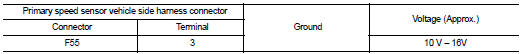
Is the inspection result normal? YES >> GO TO 2.
NO >> GO TO 6.
2. CHECK TCM INPUT SIGNAL
1. Turn ignition switch OFF.
2. Connect the primary speed sensor harness connector.
3. Start engine.
4. Lift up the vehicle.
5. Check frequency of primary speed sensor.

Is the inspection result normal? YES >> GO TO 9.
NO >> GO TO 3.
3. CHECK HARNESS BETWEEN TCM AND PRIMARY SPEED SENSOR (PART 1)
1. Turn ignition switch OFF.
2. Disconnect TCM connector and primary speed sensor harness connector.
3. Check continuity between TCM connector terminal and primary speed sensor harness connector terminal.

Is the inspection result normal? YES >> GO TO 4.
NO >> Repair or replace damaged parts.
4. CHECK HARNESS BETWEEN TCM AND PRIMARY SPEED SENSOR (PART 2)
Check continuity between TCM connector terminal and ground.

Is the inspection result normal? YES >> GO TO 5.
NO >> Repair or replace damaged parts.
5. CHECK CVT UNIT CIRCUIT
1. Disconnect CVT unit connector.
2. Check continuity between CVT unit connector terminals and ground.

Is the inspection result normal? YES >> GO TO 6.
NO >> Repair or replace damaged parts.
6. CHECK HARNESS BETWEEN PRIMARY SPEED SENSOR (POWER) AND IPDM E/R (PART 1)
1. Turn ignition switch OFF.
2. Disconnect IPDM E/R connector.
3. Check continuity between primary speed sensor vehicle side harness connector terminal and IPDM E/R vehicle side harness connector terminal.

Is the inspection result normal? YES >> GO TO 7.
NO >> Repair or replace damaged parts.
7. CHECK HARNESS BETWEEN PRIMARY SPEED SENSOR (POWER) AND IPDM E/R (PART 1)
Check continuity between primary speed sensor vehicle side harness connector terminal and ground.

Is the inspection result normal? YES >> GO TO 8.
NO >> Repair or replace damaged parts.
8.DETECT MALFUNCTIONING ITEMS
Check the following. Refer to PG-15, "Wiring Diagram - IGNITION POWER SUPPLY -".
• IPDM E/R
• 10A fuse (No.55, located in the IPDM E/R)
• Harness for short or open between IPDM E/R and ignition switch
• Ignition switch
Is the inspection result normal? YES >> Check intermittent incident. Refer to GI-42, "Intermittent Incident" NO >> Repair or replace damaged parts.
9.CHECK INTERMITTENT INCIDENT
Refer to GI-42, "Intermittent Incident".
Is the inspection result normal? YES >> Replace primary speed sensor. Refer to TM-290, "Removal and Installation".
NO >> Repair or replace damaged parts.
 P0710 transmission fluid temperature sensor A
DTC Logic
DTC DETECTION LOGIC
DTC CONFIRMATION PROCEDURE
CAUTION:
Always drive vehicle at a safe speed.
NOTE:
If “DTC CONFIRMATION PROCEDURE” has been previously performed, always turn
ignit ...
 P0717 input speed sensor A
DTC Logic
DTC DETECTION LOGIC
DTC CONFIRMATION PROCEDURE
CAUTION:
Always drive vehicle at a safe speed.
NOTE:
If “DTC CONFIRMATION PROCEDURE” has been previously performed, always turn
ignit ...
Other materials:
Door lock status indicator does not illuminate
Diagnosis Procedure
1.CHECK DOOR LOCK STATUS INDICATOR
Check door lock status indicator.
Refer to DLK-395, "Component Function Check".
Is the inspection result normal?
YES >> GO TO 2.
NO >> Repair or replace the malfunctioning parts.
2.CONFIRM THE OPERATION
Conf ...
Refilling
1. Remove filler plug (1) and gasket. Then fill oil up to mounting
hole for the filler plug.
: Vehicle front
Oil and viscosity : Refer to MA-13, "Fluids
and Lubricants".
Oil capacity : Refer to DLN-117, "General
Specifications".
CAUTION:
Carefully fill the oil. (Fill up ...
B2615 blower relay circuit
DTC Logic
DTC DETECTION LOGIC
DTC CONFIRMATION PROCEDURE
1.PERFORM DTC CONFIRMATION PROCEDURE
1. Turn ignition switch ON under the following conditions, and wait for 1
second or more.
CVT models
- Selector lever is in the P or N position
- Do not depress brake pedal
M/T models
- Do no ...