Nissan Juke Service and Repair Manual : P0444 EVAP canister purge volume control solenoid valve
DTC Logic
DTC DETECTION LOGIC

DTC CONFIRMATION PROCEDURE
1.CONDITIONING
If DTC Confirmation Procedure has been previously conducted, always turn ignition switch OFF and wait at least 10 seconds before conducting the next test.
TESTING CONDITION:
Before performing the following procedure, confirm battery voltage is more than
11 V at id
le.
>> GO TO 2.
2.PERFORM DTC CONFIRMATION PROCEDURE
1. Start engine and let it idle for at least 13 seconds.
2. Check 1st trip DTC.
Is 1st trip DTC detected? YES >> Go to EC-669, "Diagnosis Procedure".
NO >> INSPECTION END
Diagnosis Procedure
1.CHECK EVAP CANISTER PURGE VOLUME CONTROL SOLENOID VALVE POWER SUPPLY CIRCUIT
1. Turn ignition switch OFF.
2. Disconnect EVAP canister purge volume control solenoid valve harness connector.
3. Turn ignition switch ON.
4. Check the voltage between EVAP canister purge volume control solenoid valve harness connector and ground.
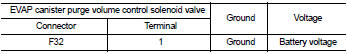
Is the inspection result normal? YES >> GO TO 3.
NO >> GO TO 2.
2.DETECT MALFUNCTIONING PART
Check the following.
• Harness for open or short between EVAP canister purge volume control solenoid
valve and IPDM E/R
• Harness for open or short between EVAP canister purge volume control solenoid
valve and ECM
>> Repair open circuit or short to ground or short to power in harness or
connectors.
3.CHECK EVAP CANISTER PURGE VOLUME CONTROL SOLENOID VALVE OUTPUT SIGNAL CIRCUIT FOR OPEN AND SHORT
1. Turn ignition switch OFF.
2. Disconnect ECM harness connector.
3. Check the continuity between EVAP canister purge volume control solenoid valve harness connector and ECM harness connector.

4. Also check harness for short to ground and short to power.
Is the inspection result normal? YES-1 >> With CONSULT-III: GO TO 4.
YES-2 >> Without CONSULT-III: GO TO 5.
NO >> Repair open circuit or short to ground or short to power in harness or connectors.
4.CHECK EVAP CANISTER PURGE VOLUME CONTROL SOLENOID VALVE OPERATION
 With CONSULT-III
1. Reconnect all harness connectors disconnected.
2. Start engine.
3. Perform “PURG VOL CONT/V” in “ACTIVE TEST” mode with CONSULT-III. Check that engine speed varies according to the valve opening.
Does engine speed vary according to the valve opening? YES >> GO TO 6.
NO >> GO TO 5.
5.CHECK EVAP CANISTER PURGE VOLUME CONTROL SOLENOID VALVE
Refer to EC-670, "Component Inspection".
Is the inspection result normal? YES >> GO TO 6.
NO >> Replace EVAP canister purge volume control solenoid valve.
6.CHECK INTERMITTENT INCIDENT
Refer to GI-42, "Intermittent Incident".
>> INSPECTION END
Component Inspection
1.CHECK EVAP CANISTER PURGE VOLUME CONTROL SOLENOID VALVE
 With CONSULT-III
1. Turn ignition switch OFF.
2. Reconnect all harness connectors disconnected.
3. Disconnect EVAP purge hoses connected to EVAP canister purge volume control solenoid valve.
4. Turn ignition switch ON.
5. Select “PURG VOL CONT/V” in “ACTIVE TEST” mode with CONSULT-III.
6. Touch “Qd” and “Qu” on CONSULT-III screen to adjust “PURG VOL C/V” opening and check air passage continuity of EVAP canister purge volume control solenoid valve under the following conditions.


 Without CONSULT-III
1. Turn ignition switch OFF.
2. Disconnect EVAP canister purge volume control solenoid valve harness connector.
3. Disconnect EVAP purge hoses connected to EVAP canister purge volume control solenoid valve.
4. Check air passage continuity of EVAP canister purge volume control solenoid valve under the following conditions.


Is the inspection result normal? YES >> INSPECTION END
NO >> Replace EVAP canister purge volume control solenoid valve
 P0420 three way catalyst function
DTC Logic
DTC DETECTION LOGIC
The ECM monitors the switching frequency ratio of air fuel ratio (A/F)
sensor 1 and heated oxygen sensor 2.
A three way catalyst (manifold) with high oxygen storage ...
 P0500 VSS
Description
The vehicle speed signal is sent to the combination meter from the “ABS
actuator and electric unit (control
unit)” by CAN communication line. The combination meter then sends a signal ...
Other materials:
P0710 transmission fluid temperature sensor A
DTC Logic
DTC DETECTION LOGIC
DTC CONFIRMATION PROCEDURE
CAUTION:
Always drive vehicle at a safe speed.
NOTE:
If “DTC CONFIRMATION PROCEDURE” has been previously performed, always turn
ignition switch
OFF and wait at least 10 seconds before performing the next test.
After the repair, p ...
C1142 press sensor
DTC Logic
DTC DETECTION LOGIC
DTC CONFIRMATION PROCEDURE
1.PRECONDITIONING
If “DTC CONFIRMATION PROCEDURE” has been previously conducted, always turn
ignition switch OFF and
wait at least 10 seconds before conducting the next test.
>> GO TO 2.
2.CHECK DTC DETECTION
With CONSULT ...
The key warning does not sound (without intelligent key)
Description
The key warning chime does not sound, when all of the following conditions
are fulfilled.
• Key inserted into the key cylinder (key switch signal ON).
• Ignition switch is in ACC or OFF (ignition switch signal OFF).
• Driver side door is open (driver side door switch ON)
Diagnos ...