Nissan Juke Service and Repair Manual : P0045 TC boost control solenoid valve
DTC Logic
DTC DETECTION LOGIC
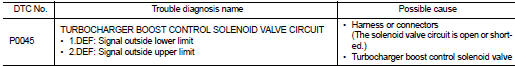
Diagnosis Procedure
1.CHECK TURBOCHARGER BOOST CONTROL SOLENOID VALVE POWER SUPPLY CIRCUIT
1. Turn ignition switch OFF.
2. Disconnect turbocharger boost control solenoid valve harness connector.
3. Turn ignition switch ON.
4. Check the voltage between turbocharger boost control solenoid valve harness connector and ground.

Is the inspection result normal? YES >> GO TO 3.
NO >> GO TO 2.
2.DETECT MALFUNCTIONING PART
Check the following.
• Harness for open or short between IPDM E/R and turbocharger boost control solenoid valve
>> Repair open circuit or short to ground or short to power in harness or connectors.
3.CHECK TURBOCHARGER BOOST CONTROL SOLENOID VALVE OUTPUT SIGNAL CIRCUIT FOR OPEN AND SHORT
1. Turn ignition switch OFF.
2. Disconnect ECM harness connector.
3. Check the continuity between turbocharger boost control solenoid valve harness connector and ECM harness connector.

4. Also check harness for short to ground and short to power.
Is the inspection result normal? YES >> GO TO 4.
NO >> Repair open circuit or short to ground or short to power in harness or connectors.
4.CHECK TURBOCHARGER BOOST CONTROL SOLENOID VALVE
Refer to EC-894, "Component Inspection".
Is the inspection result normal? YES >> GO TO 5.
NO >> Replace turbocharger boost control solenoid valve.
5.CHECK INTERMITTENT INCIDENT
Refer to GI-42, "Intermittent Incident", ???INCIDENT SIMULATION TESTS??? and ???GROUND INSPECTION???.
>> INSPECTION END
Component Inspection
1.CHECK TURBOCHARGER BOOST CONTROL SOLENOID VALVE
1. Turn ignition switch OFF.
2. Disconnect turbocharger boost control solenoid valve harness connector.
3. Check resistance between turbocharger boost control solenoid valve terminals as follows.
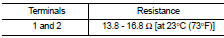
Is the inspection result normal? YES >> INSPECTION END
NO >> Replace turbocharger boost control solenoid valve.
 P0016 CKP - CMP correlation
DTC Logic
DTC DETECTION LOGIC
Diagnosis Procedure
1.CHECK CKP SENSOR AND CMP SENSOR
Refer to EC-932, "Diagnosis Procedure" (CKP sensor) and EC-934, "Diagnosis
Procedure" (C ...
 P0087 fuel pump
DTC Logic
DTC DETECTION LOGIC
NOTE:
• Conditions for applying the diagnostic procedure to the stored DTCs:
The DTC becomes present during the first 30 seconds after the engine starts.
• In low ...
Other materials:
Encoder circuit
Component Function Check
1.CHECK ENCODER OPERATION
Check that front driver side door glass perform AUTO UP/DOWN operation
normally when power window
main switch is operated.
Is the inspection result normal?
YES >> INSPECTION END
NO >> Refer to PWC-30, "Diagnosis Procedure& ...
Basic inspection
Work Procedure
1.INSPECTION START
1. Check service records for any recent repairs that may indicate a related
malfunction, or a current need for
scheduled maintenance.
2. Open engine hood and check the following:
- Harness connectors for improper connections
- Wiring harness for improper con ...
U1000 can comm circuit
Description
CAN (Controller Area Network) is a serial communication line for real time
applications. It is an on-board multiplex
communication line with high data communication speed and excellent error
detection ability. A modern
vehicle is equipped with many ECUs, and each control unit shar ...