Nissan Juke Service and Repair Manual : LAN System can system (type 7)
DTC/CIRCUIT DIAGNOSIS
Main line between IPDM-E and DLC circuit
Diagnosis Procedure
1.CHECK CONNECTOR
1. Turn the ignition switch OFF.
2. Disconnect the battery cable from the negative terminal.
3. Check the following terminals and connectors for damage, bend and loose connection (connector side and harness side).
- Harness connector E105 - Harness connector M77
Is the inspection result normal? YES >> GO TO 2.
NO >> Repair the terminal and connector.
2.CHECK HARNESS CONTINUITY (OPEN CIRCUIT)
1. Disconnect the following harness connectors.
- IPDM E/R
- Harness connectors E105 and M77
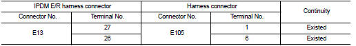
2. Check the continuity between the IPDM E/R harness connector and the harness
connector.
Is the inspection result normal? YES >> GO TO 3.
NO >> Repair the main line between the IPDM E/R and the harness connector E105.
3.CHECK HARNESS CONTINUITY (OPEN CIRCUIT)
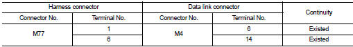
Check the continuity between the harness connector and the data link connector.
Is the inspection result normal? YES (Present error)>>Check CAN system type decision again.
YES (Past error)>>Error was detected in the main line between the IPDM E/R and the data link connector.
NO >> Repair the main line between the harness connector M77 and the data link connector.
Main line between DLC and MDU circuit
Diagnosis Procedure
1.CHECK HARNESS CONTINUITY (OPEN CIRCUIT)
1. Turn the ignition switch OFF.
2. Disconnect the battery cable from the negative terminal.
3. Disconnect the following harness connectors.
- ECM
- Multi display unit
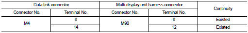
4. Check the continuity between the data link connector and the multi display
unit harness connector.
Is the inspection result normal? YES (Present error)>>Check CAN system type decision again.
YES (Past error)>>Error was detected in the main line between the the data link connector and the multi display unit.
NO >> Repair the main line between the data link connector and the multi display unit.
 LAN System can system (type 6)
DTC/CIRCUIT DIAGNOSIS
Main line between IPDM-E and DLC circuit
Diagnosis Procedure
1.CHECK CONNECTOR
1. Turn the ignition switch OFF.
2. Disconnect the battery cable from the negative terminal.
...
 ECM branch line circuit
Diagnosis Procedure
1.CHECK CONNECTOR
1. Turn the ignition switch OFF.
2. Disconnect the battery cable from the negative terminal.
3. Check the terminals and connectors of the ECM for damage, bend ...
Other materials:
Heated seats (if so equipped)
WARNING
Do not use or allow occupants to use the seat heater if you or the occupants
cannot monitor elevated seat temperatures or have an inability to feel pain in body
parts that contact the seat. Use of the seat heater by such people could result
in serious injury.
CAUTION
• The battery c ...
System
Intelligent key system/engine start function
INTELLIGENT KEY SYSTEM/ENGINE START FUNCTION : System Diagram
INTELLIGENT KEY SYSTEM/ENGINE START FUNCTION : System
SYSTEM DESCRIPTION
• The engine start function of Intelligent Key system makes it possible to
start and stop the engine without
us ...
B1137 side air bag module LH
DTC Logic
DTC DETECTION LOGIC
DTC CONFIRMATION PROCEDURE
1.CHECK SELF-DIAG RESULT
With CONSULT-III
1. Turn ignition switch ON.
2. Perform “Self Diagnostic Result” mode of “AIR BAG” using CONSULT-III.
Without CONSULT-III
1. Turn ignition switch ON.
2. Check the air bag warning lamp statu ...