Nissan Juke Service and Repair Manual : Intelligent key warning buzzer
Component Function Check
1.CHECK FUNCTION
1. Select “INTELLIGENT KEY” of “BCM” using CONSULT-III.
2. Select “OUTSIDE BUZZER” in “ACTIVE TEST” mode.
3. Check that the function operates normally according to the following conditions.

Is the inspection result normal? YES >> Intelligent Key warning buzzer is OK.
NO >> Refer to DLK-263, "Diagnosis Procedure".
Diagnosis Procedure
1.CHECK FUSE
1. Turn ignition switch OFF.
2. Check 10 A fuse, [No. 7, located in fuse block (J/B)].
Is the inspection result normal? YES >> GO TO 2.
NO >> Replace the blown fuse after repairing the affected circuit if a fuse is blown.
2.CHECK INTELLIGENT KEY WARNING BUZZER POWER SUPPLY CIRCUIT
1. Disconnect Intelligent Key warning buzzer connector.
2. Check voltage between Intelligent Key warning buzzer harness connector and ground.

Is the inspection result normal? YES >> GO TO 3.
NO >> Repair or replace harness.
3.CHECK INTELLIGENT KEY WARNING BUZZER CIRCUIT
1. Disconnect BCM connector.
2. Check continuity between BCM harness connector and Intelligent Key warning buzzer harness connector.

3. Check continuity between BCM harness connector and ground.
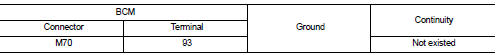
Is the inspection result normal? YES >> GO TO 4.
NO >> Repair or replace harness.
4.CHECK INTELLIGENT KEY WARNING BUZZER
Refer to DLK-264, "Component Inspection".
Is the inspection result normal? YES >> Replace BCM. Refer to BCS-93, "Removal and Installation".
NO >> Replace Intelligent Key warning buzzer.
Component Inspection
1.CHECK INTELLIGENT KEY WARNING BUZZER
1. Turn ignition switch OFF.
2. Disconnect Intelligent Key warning buzzer connector.
3. Connect battery power supply directly to Intelligent Key warning buzzer terminals and check the operation.

Is the inspection result normal? YES >> INSPECTION END
NO >> Replace Intelligent Key warning buzzer.
 Intelligent key
Component Function Check
1.CHECK FUNCTION
1. Select “INTELLIGENT KEY” of “BCM” using CONSULT-III.
2. Select “RKE OPE COUN1” in “DATA MONITOR” mode.
3. Check that the function operates normally acc ...
 Key warning lamp
Component Function Check
1.CHECK FUNCTION
1. Select “INTELLIGENT KEY” of “BCM” using CONSULT-III.
2. Select “INDICATOR” in “ACTIVE TEST” mode.
3. Check that the function operates normally accordin ...
Other materials:
Front disc brake
Brake pad : Exploded View
MR16DDT
1. Cylinder body
2. Inner shim
3. Inner pad (with pad wear sensor)
4. Pad retainer
5. Torque member
6. Outer pad
7. Outer shim
1: Apply MOLYKOTE® AS880N or
silicone-based grease.
2: Apply MOLYKOTE® 7439 or
equivalent.
: N·m (kg-m, ft-lb)
HR16DE ...
Fender protector
Exploded View
1. Hoodledge insurator
2. Fender protector
3. U nut
4. Air guide
5. Screw grommet
A. To hoodledge panel
: Vehicle front
Removal and Installation
REMOVAL
1. Remove front fillet molding. Refer to EXT-26, "FRONT FILLET MOLDING :
Removal and Installation".
2. Re ...
P1726 throttle control signal
Description
Electric throttle control actuator consists of throttle control motor,
accelerator pedal position sensor, throttle
position sensor etc. The actuator sends a signal to the ECM, and ECM sends the
signal to TCM with CAN
communication.
DTC Logic
DTC DETECTION LOGIC
DTC CONFIRMATI ...