Nissan Juke Service and Repair Manual : Heater control
Exploded View
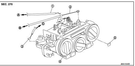
1. Intake door cable
2. Air mix door cable
3. Mode door cable
4. Heater control
5. Intake door lever knob
A. To intake door link B. To air mix door link C. To mode door link
Removal and Installation
REMOVAL
1. Remove A/C finisher. Refer to IP-13, "Removal and Installation".
2. Remove heater control fixing screws (A) and fixing pawls, and then remove heater control.
 : Pawl

3. Disconnect door cable and harness connector from heater control.
INSTALLATION
Install in the reverse order of removal.

 Blower fan resistor
Exploded View
1. Heater unit assembly
2. Fan control amp.*1
3. Blower fan resistor*2
4. Blower motor
5. Blower motor cover
• *1: Automatic air conditioner
• *2: Manual air conditioner or M ...
Other materials:
Child safety
WARNING
Do not allow children to play with the seat belts. Most seating positions
are equipped with Automatic Locking Retractor (ALR) mode seat belts. If the seat
belt becomes wrapped around a child’s neck with the ALR mode activated, the child
can be seriously injured or killed if the seat b ...
B1180 lap Pre-tensioner RH
DTC Logic
DTC CONFIRMATION PROCEDURE
1.CHECK SELF-DIAGNOSTIC RESULT
With CONSULT-III
1. Turn ignition switch ON.
2. Perform “Self Diagnostic Result” mode of “AIR BAG” using CONSULT-III.
Without CONSULT-III
1. Turn ignition switch ON.
2. Check the air bag warning lamp status. Refer to SRC ...
ABS warning lamp
Component Function Check
1.CHECK ABS WARNING LAMP FUNCTION
Check that ABS warning lamp in combination meter turns ON for approx. 1
second after ignition switch is
turned ON.
CAUTION:
Never start engine.
Is the inspection result normal?
YES >> INSPECTION END
NO >> Proceed to B ...