Nissan Juke Service and Repair Manual : Front wiper drive assembly
Exploded View
REMOVAL
LHD models
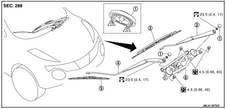
1. Front wiper arm cap
2. Front wiper arm LH
3. Front wiper blade LH
4. Front wiper arm RH
5. Front wiper blade RH
6. Front wiper drive assembly
 : Pawl
 : N·m (kg-m, in-lb)
 : N·m (kg-m, ft-lb)
RHD models

1. Front wiper arm cap
2. Front wiper arm RH
3. Front wiper drive assembly
4. Front wiper motor
5. Front wiper blade LH
6. Front wiper arm LH
7. Front wiper blade RH
 : Pawl
 : N·m (kg-m, in-lb)
 : N·m (kg-m, ft-lb)
DISASSEMBLY
LHD models

1. Front wiper linkage 1
2. Shaft seal
3. Front wiper frame
4. Front wiper motor
5. Front wiper linkage 2
6. Front wiper arm LH
 : Nissan MP special grease No
RHD models

1. Front wiper linkage 1
2. Shaft seal
3. Front wiper frame
4. Front wiper motor
5. Front wiper linkage 2
6. Front wiper arm LH
 : Nissan MP special grease No.2
Removal and Installation
REMOVAL
1. Remove front wiper arms (LH and RH). Refer to WW-76, "Removal and Installation".
2. Remove cowl top cover. Refer to EXT-20, "Removal and Installation".
3. Disconnect the front wiper motor connector.
4. Remove the mounting bolts from front wiper drive assembly.
5. Remove the front wiper drive assembly from the vehicle.
INSTALLATION
1. Install the front wiper drive assembly to the vehicle.
2. Connect front wiper motor connector.
3. Operate front wiper to move it to the auto stop position.
4. Install cowl top cover. Refer to EXT-20, "Removal and Installation".
5. Install front wiper arms. Refer to WW-76, "Removal and Installation".
Disassembly and Assembly
DISASSEMBLY
1. Remove the front wiper linkage 1 and 2 from the front wiper drive assembly.
CAUTION:
Never bend the linkage or damage the plastic part of the ball joint when
removing the wiper linkage.
2. Remove the front wiper motor mounting screws, and then remove the front wiper motor from the front wiper frame.
ASSEMBLY
1. Connect the front wiper motor connector.
2. Operate the front wiper to move it to the auto stop position.
3. Disconnect the front wiper motor connector.
4. Install the front wiper motor to the front wiper frame.
5. Install the front wiper linkage 2 to the front wiper motor and the front wiper frame.
6. Install the front wiper linkage 1 to the front wiper frame.
CAUTION:
• Never drop front wiper motor or cause it to come into contact with other
parts.
• Be careful for the grease condition at the front wiper motor and front wiper linkage joint (retainer). Apply Multi−purpose grease or an equivalent if necessary.
 Front wiper blade
Exploded View
1. Wiper blade
2. Wiper arm
Removal and Installation
REMOVAL
Push up the lever (A) of wiper blade (1), while sliding wiper blade
toward the direction of the arrow to remove it f ...
 Light & rain sensor
Exploded View
1. Light & rain sensor bracket
2. Mirror base
3. Light & rain sensor
4. Inside mirror assembly
: Pawl
: Do not reuse
Removal and Installation
CAUTION:
When the light ...
Other materials:
Main power supply and ground circuit
Diagnosis Procedure
1.CHECK TCM POWER CIRCUIT 1
1. Turn the ignition switch OFF.
2. Disconnect the TCM connector.
3. Check the voltage between the TCM harness connector terminals and ground.
Is the inspection result normal?
YES >> GO TO 2.
NO >> GO TO 4.
2.CHECK TCM POWER C ...
Service data and specifications (SDS)
Wheel Bearing
Drive Shaft
*: For measuring position, refer to FAX-81, "WHEEL SIDE : Disassembly and
Assembly" (Wheel side), FAX-
84, "TRANSAXLE SIDE : Disassembly and Assembly" (Transaxle side). ...
P062f eeprom
DTC Logic
DTC DETECTION LOGIC
DTC CONFIRMATION PROCEDURE
1.PREPARATION BEFORE WORK
If another "DTC CONFIRMATION PROCEDURE" occurs just before, turn ignition
switch OFF and wait for at
least 10 seconds, then perform the next test.
>> GO TO 2.
2.CHECK DTC DETECTION
1. S ...