Nissan Juke Service and Repair Manual : Front door lock
Exploded View

1. Door key cylinder assembly (driver
side)
Outside handle escutcheon (passenger
side)
2. Rear gasket
3. Outside handle bracket
4. TORX bolt
5. Key rod (driver side)
6. Door lock assembly
7. Inside handle
8. Outside handle
9. Front gasket
10. Cable clip
 : Pawl
 : Vehicle front
 : Do not reuse
 : N·m (kg-m, in-lb)
 : Body grease
Door lock
DOOR LOCK : Removal and Installation
REMOVAL
1. Remove front door glass and front door lower sash (rear). Refer to GW-17, "Removal and Installation".
2. Remove inside handle. Refer to DLK-590, "INSIDE HANDLE : Removal and Installation".
3. Disengage inside handle cable and lock knob cable from cable clip.
4. Remove outside handle bracket. Refer to DLK-590, "OUTSIDE HANDLE : Removal and Installation".
5. Remove door lock assembly TORX bolts.
6. Disconnect door lock actuator connector, and then remove door lock assembly.
INSTALLATION
Note the following items, and install in the reverse order of removal.
CAUTION:
• Never reuse TORX bolt. Always replace it with a new one when it is removed.
• Check door open/close, lock/unlock operation after installation.
• Check door lock cable is properly engaged with outside handle bracket.
• Check door lock assembly for poor lubrication. Apply body grease to door lock if necessary.
 : Grease up point

Inside handle
INSIDE HANDLE : Removal and Installation
REMOVAL
1. Remove front door finisher. Refer to INT-13, "Removal and Installation".
2. Remove inside handle mounting bolt (A).
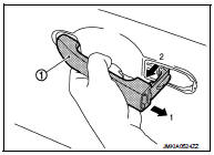
3. Disengage inside handle (1) from door panel (2) while sliding inside handle toward vehicle rear, and then separate inside handle.
 : Vehicle front

4. Disengage inside handle cable (3) and lock knob cable (2), and then remove inside handle (1).

INSTALLATION
Note the following item, and install in the reverse order of removal.
CAUTION:
Check door open/close, lock/unlock operation after installation.
Outside handle
OUTSIDE HANDLE : Removal and Installation
REMOVAL
1. Fully close the front door glass.
2. Remove front door finisher. Refer to INT-13, "Removal and Installation".
3. Remove sealing screen.
NOTE
:
Cut the butyl-tape so that some parts of the butyl-tape do not remain on the
sealing screen, if the sealing
screen is reused.
4. Disengage lock holder (1), and then separate key rod (3) from door lock assembly (2).(Driver side)

5. Remove grommet (1) of door side. Loosen, through grommet hole, TORX bolt (2) that fixes door lock cylinder. (For passenger side, TORX bolt fixes outside handle escutcheon.)

6. While pulling outside handle, remove door key cylinder assembly (diver side) or outside handle escutcheon (passenger side).

7. While pulling outside handle (1), slide toward rear of vehicle to remove outside handle.
8. Remove front gasket (1) and rear gasket (2).
 : Vehicle front

9. Slide outside handle bracket toward rear of vehicle to remove.
 : Vehicle front

10. Disconnect outside handle cable (1) from outside handle bracket (2).

INSTALLATION
Note the following items, and install in the reverse order of removal.
CAUTION:
• When installing key rod, rotate key rod holder until a click is felt.
• Check that door lock cables are normally engaged with inside handle and outside handle.
• After installation, check door open/close, and lock/unlock operation.
 Hood lock
Exploded View
1. Hood lock control cable assembly
2. Hood lock assembly
: Clip
: N·m (kg-m, ft-lb)
: Body grease
Hood lock
HOOD LOCK : Removal and Installation
REMOVAL
1. Remove front cent ...
 Rear door lock
Exploded View
1. Outside handle assembly
2. Rear door sealing screen
3. Door lock assembly
4. TORX bolt
5. Inside handle
: Clip
: Pawl
: Vehicle front
: Do not reuse
: N·m (kg-m, in-lb) ...
Other materials:
P0641 sensor power supply
DTC Logic
DTC DETECTION LOGIC
Diagnosis Procedure
1.CHECK GROUND CONNECTION
1. Turn ignition switch OFF.
2. Check ground connection E38. Refer to Ground Inspection in GI-44, "Circuit
Inspection".
Is the inspection result normal?
YES >> GO TO 2.
NO >> Repair or r ...
Diagnosis and repair work flow
Flowchart of Trouble Diagnosis
NOTE:
“DTC” includes DTC at the 1st trip.
1.OBTAIN INFORMATION ABOUT SYMPTOM
1. Refer to TM-372, "Question sheet" and interview the customer to obtain the
malfunction information (conditions
and environment when the malfunction occurred) as much as p ...
General maintenance
During the normal day-to-day operation of the vehicle, general maintenance should
be performed regularly as prescribed in this section. If you detect any unusual
sounds, vibrations or smell, be sure to check for the cause or have a NISSAN dealer
do it promptly. In addition, you should notify a ...