Nissan Juke Service and Repair Manual : Fluid cooler system
Exploded View

1. Copper washer
2. CVT fluid cooler tube
3. Hose clamp
4. Fluid cooler hose A
5. Fluid cooler tube
6. Fluid cooler hose B
7. Fluid cooler hose C
8. Transaxle assembly
9. Fluid cooler hose D
10. Fluid cooler hose E
11. Fluid cooler hose F
12. Bypass valve
13. Fluid cooler
14. Air guide
15. Bracket A
16. Bracket B
A. To radiator
 : Vehicle side
Removal and Installation
REMOVAL
1. Remove engine under cover.
2. Remove front bumper assembly. Refer to EXT-13, "Removal and Installation".
3. Remove air guide from fluid cooler.
4. Remove fluid cooler hose E and fluid cooler hose F.
5. Remove fluid cooler.
6. Remove air duct (inlet). Refer to EM-26, "Removal and Installation".
7. Remove fluid cooler hose C and fluid cooler hose D.
8. Remove bypass valve from bracket B.
9. Remove fluid cooler hose A and fluid cooler hose B.
10. Remove fluid cooler tube.
11. Remove bracket A and bracket B.
12. Remove CVT fluid cooler tube from transaxle assembly.
INSTALLATION
Note the following, and install in the reverse order of removal.
CAUTION:
Never reuse copper washer.
• When installing CVT fluid cooler tube (1) to transaxle assembly: - Contact CVT fluid cooler tube a boss portion (A) of the transaxle case.
- Tighten the bolt of CVT fluid cooler tube without moving the CVT fluid cooler tube

• Refer to the followings when installing fluid cooler hose.
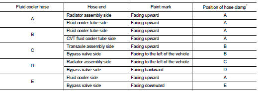

*: Refer to the illustrations for the specific position each hose clamp tab.
- The illustrations indicate the view from the hose ends.
F : Vehicle upper
 G : Vehicle front
- When installing hose clamps center line of each hose clamp tab should be positioned as shown in the figure.

- Insert fluid cooler hose according to dimension (L) described below.


- Set hose clamps (1) at the both ends of fluid cooler hose (2) with dimension (A) from the hose edge.

- Hose clamp should not interfere with the bulge of fluid cooler tube.

Inspection
INSPECTION AFTER INSTALLATION
Check for CVT fluid leakage and CVT fluid level. Refer to TM-184, "Inspection".
 Water hose
Exploded View
1. Hose clamp
2. Water hose
A. Water outlet
B. Oil warm
Removal and Installation
REMOVAL
WARNING:
Never remove the radiator cap when the engine is hot. Serious burns could oc ...
 Unit removal and installation
Transaxle assembly
Exploded View
1. CVT fluid level gauge
2. CVT fluid charging pipe
3. O-ring
4. Transaxle assembly
5. Air breather hose
A. For tightening torque, refer to TM-301, "R ...
Other materials:
Back door opener actuator
Component Function Check
1.CHECK FUNCTION
1. Select “INTELLIGENT KEY” of “BCM” using CONSULT-III.
2. Select “TRUNK/BACK DOOR” in “ACTIVE TEST” mode.
3. Check that the function operates normally according to the following
conditions.
Is the inspection result normal?
YES >> Back door o ...
Compressor dose dot operate
Description
SYMPTOM
Compressor dose not operate.
Diagnosis Procedure
NOTE:
• Perform self-diagnosis with CONSULT-III before performing symptom diagnosis.
If any malfunction result or
DTC is detected, perform the corresponding diagnosis.
• Check that refrigerant is enclosed in cooler cycle n ...
ANTI-HIJACK function does not operate
Diagnosis Procedure
1.CHECK “DOOR LOCK–UNLOCK SET” SETTING IN “WORK SUPPORT”
1. Select “DOOR LOCK” of “BCM” using CONSULT-III.
2. Select “DOOR LOCK-UNLOCK SET” in “WORK SUPPORT” mode.
3. Check “DOOR LOCK-UNLOCK SET” in “WORK SUPPORT”
Refer to DLK-501, "DOOR LOCK : CONSULT-III Function (BCM ...