Nissan Juke Service and Repair Manual : ECU diagnosis information
IPDM E/R
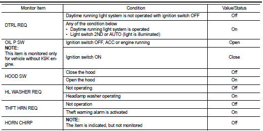
Reference Value
VALUES ON THE DIAGNOSIS TOOL

TERMINAL LAYOUT

PHYSICAL VALUES


*1: MR16DDT engine models
*2: Except MR16DDT engine models
*3: CVT models
*4: M/T models
*5: With daytime running light system
*6: Without daytime running light system
*7: K9K engine models
Fail-Safe
CAN COMMUNICATION CONTROL
When CAN communication with ECM and BCM is impossible, IPDM E/R performs fail-safe control. After CAN communication recovers normally, it also returns to normal control.
If No CAN Communication Is Available With ECM

If No CAN Communication Is Available With BCM

IGNITION RELAY MALFUNCTION DETECTION FUNCTION
• IPDM E/R monitors the voltage at the contact circuit and excitation coil circuit of the ignition relay inside it.
• IPDM E/R judges the ignition relay error if the voltage differs between the contact circuit and the excitation coil circuit.
• If the ignition relay cannot turn OFF due to contact seizure, it activates the tail lamp relay for 10 minutes to alert the user to the ignition relay malfunction when the ignition switch is turned OFF.

FRONT WIPER PROTECTION FUNCTION
IPDM E/R detects front wiper stop position by a front wiper stop position signal.
When a front wiper stop position signal is in the conditions listed below, IPDM E/R stops power supply to wiper after repeating a front wiper 10 seconds activation and 20 seconds stop.

NOTE
:
This operation status can be confirmed on the IPDM E/R “Data Monitor” that
displays “BLOCK” for the item
“WIP PROT” while the wiper is stopped.
STARTER MOTOR PROTECTION FUNCTION
IPDM E/R turns OFF the starter control relay to protect the starter motor when the starter control relay remains active for 90 seconds.
DTC Index
NOTE
:
• The details of time display are as follows.
- CRNT: A malfunction is detected now.
- PAST: A malfunction was detected in the past.
• IGN counter is displayed on FFD (Freeze Frame Data).
- The number is 0 when is detected now.
- The number increases like 1 → 2 ··· 38 → 39 after returning to the normal condition whenever IGN OFF → ON.
- The number is fixed to 39 until the self-diagnosis results are erased if it is over 39.

 Diagnosis system (IPDM E/R)
Diagnosis Description
AUTO ACTIVE TEST
Description
In auto active test mode, the IPDM E/R sends a drive signal to the following
systems to check their operation.
• Oil pressure warning lamp (o ...
 Wiring diagram
IPDM E/R
Wiring Diagram
For connector terminal arrangements, harness layouts, and alphabets in a
(option abbreviation; if not
described in wiring diagram), refer to GI-12, "Connector Informat ...
Other materials:
Refilling
1. Remove filler plug (1). Fill with new gear oil until oil level reaches
the specified level near filler plug mounting hole
Oil grade and viscosity : Refer to MA-13, "Fluids
and Lubricants".
Oil capacity : Refer to DLN-167, "General
Specification".
2. After refilling oil, ...
Headlamp
Exploded View
REMOVAL
1. Headlamp assembly
2. EPT sealer [2.8 mm (0.110 in)]
: Do not reuse
: N·m (kg-m, in-lb)
DISASSEMBLY
1. Back cover
2. Halogen bulb
3. Headlamp housing assembly
4. Retaining spring
5. EPT sealer [2.8 mm (0.110 in)]
: Do not reuse
Removal and Installation
C ...
Precaution for Supplemental Restraint System (SRS) "AIR BAG" and "SEAT BELT
PRE-TENSIONER"
The Supplemental Restraint System such as “AIR BAG” and “SEAT BELT PRE-TENSIONER”,
used along
with a front seat belt, helps to reduce the risk or severity of injury to the
driver and front passenger for certain
types of collision. Information necessary to service the system safely is
include ...