Nissan Juke Service and Repair Manual : ECU diagnosis information
DIAGNOSIS SENSOR UNIT
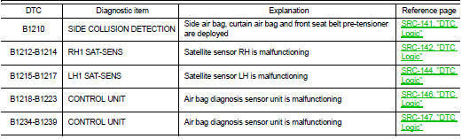
DTC Index


 Diagnosis system (air bag)
Description
CAUTION:
• Never use electrical test equipment on any circuit related to the SRS unless
instructed in this Service
Manual. SRS wiring harnesses can be identified by yellow and/or oran ...
 Wiring diagram
SRS AIR BAG SYSTEM
Wiring Diagram
For connector terminal arrangements, harness layouts, and alphabets in a
(option abbreviation; if not
described in wiring diagram), refer to GI-12, "Connect ...
Other materials:
Wiring diagram
CHARGING SYSTEM
Wiring Diagram
GASOLINE ENGINE MODELS
For connector terminal arrangements, harness layouts, and alphabets in a
(option abbreviation; if not
described in wiring diagram), refer to GI-12, "Connector Information/Explanation
of Option Abbreviation".
DIESEL ENGINE MOD ...
System
System Description
SYSTEM DIAGRAM
• The multi display unit transmits the operation status of the drive mode
switch to other units via CAN communication
as the mode signal (refer below).
- NORMAL: ON/OFF
- SPORT: ON/OFF
- ECO: ON/OFF
• Based on the mode signals received from TCM (CVT mod ...
Component parts
Manual air conditioning system : Component Part Location
1. BCM
• With Intelligent Key: Refer to BCS-
6, "BODY CONTROL SYSTEM :
Component Parts Location".
• Without Intelligent Key: Refer to
BCS-161, "Removal and Installation".
2. Magnet clutch
3. Refrigerant pressure ...