Nissan Juke Service and Repair Manual : DTC/Circuit diagnosis
POSITION SWITCH
BACK-UP LAMP SWITCH : Component Inspection
1.CHECK BACK-UP LAMP SWITCH
1. Disconnect position switch connector. Refer to TM-24, "Removal and Installation".
2. Check continuity between position switch terminals.
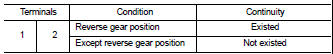

Is the inspection result normal? YES >> INSPECTION END
NO >> Replace position switch. Refer to TM-24, "Removal and Installation".
PARK/NEUTRAL POSITION (PNP) SWITCH : Component Inspection
1.CHECK PARK/NEUTRAL POSITION (PNP) SWITCH
1. Disconnect position switch connector. Refer to TM-24, "Removal and Installation".
2. Check continuity between position switch terminals.


Is the inspection result normal? YES >> INSPECTION END
NO >> Replace position switch. Refer to TM-24, "Removal and Installation".
 Structure and operation
Sectional View
1. 5th input gear
2. 5th-reverse synchronizer hub assembly
3. Input shaft
4. Mainshaft
5. 5th main gear
6. Mainshaft rear bearing
7. 4th main gear
8. 3rd-4th synchronizer ...
 Symptom diagnosis
NOISE, VIBRATION AND HARSHNESS (NVH) TROUBLESHOOTING
NVH Troubleshooting Chart
Use the chart below to find the cause of the symptom. The numbers indicate
the order of the inspection. If necessary, ...
Other materials:
P0720 output speed sensor
DTC Logic
DTC DETECTION LOGIC
DTC CONFIRMATION PROCEDURE
CAUTION:
Always drive vehicle at a safe speed.
NOTE:
If “DTC CONFIRMATION PROCEDURE” has been previously performed, always turn
ignition switch
OFF and wait at least 10 seconds before performing the next test.
After the repair, p ...
U1000 can comm circuit
Description
CAN (Controller Area Network) is a serial communication line for real time
application. It is an on-vehicle multiplex
communication line with high data communication speed and excellent error
detection ability. Many electronic
control units are equipped onto a vehicle, and each co ...
No engine braking
Description
CHART 11: NO ENGINE BRAKING
Diagnosis Procedure
1.CHECK ECM POWER SUPPLY AND GROUND CIRCUIT
Check ECM power supply and ground circuit. Refer to EC-885, "Diagnosis
Procedure".
Is the inspection result normal?
YES >> GO TO 2.
NO >> Repair or replace harne ...