Nissan Juke Service and Repair Manual : Door outside molding
Exploded View

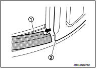
1. Front door panel
2. Front door outside molding
3. Rear door panel
4. Rear door outside molding
5. Door glass
 : Pawl
Front door outside molding
FRONT DOOR OUTSIDE MOLDING : Removal and Installation
REMOVAL
1. Fully open front door glass.
2. Twist door outside molding toward the outside of the vehicle, and then lift up and remove it while disengaging the pawls.

INSTALLATION
Note the following item, and then install in the reverse order of removal.
CAUTION
:
When installing front door outside molding, check that pawl (1)
is accurately aligned with mounting hole (2), then press in.

Rear door outside molding
REAR DOOR OUTSIDE MOLDING : Removal and Installation
REMOVAL
1. Fully open rear door glass.
2. Twist rear door outside molding toward vehicle outside and remove molding while disengaging it from door panel.
 : Pawl

3. Slide rear door outside molding (1) toward vehicle front, and then pull molding out from rear door handle (2).
INSTALLATION
Note the following item, and then install in the reverse order of removal.
CAUTION:
When installing rear door outside molding, check that pawl (1)
is accurately aligned with mounting hole (2), then press in.

 Roof side molding
Exploded View
1. Roof side molding
2. Roof side molding clip
3. Double-sided tape [t: 2.5 mm (0.098 in)]
4. Body side outer panel
5. Roof panel
: Vehicle front
: Do not reuse
Removal and ...
 Door sash tape
Exploded View
1. Front door panel
2. Front door sash tape
3. Rear door sash tape
4. Rear door panel
: Do not reuse
Front door sash tape
FRONT DOOR SASH TAPE : Removal and Installation
REMO ...
Other materials:
How to select piston and bearing
Description
• The identification grade stamped on each part is the grade for the
dimension measured in new condition. This grade cannot apply to reused parts.
• For reused or repaired parts, measure the dimension accurately. Determine the
grade by comparing the
measurement with the values o ...
Air conditioning cut control
Air conditioning cut control : System Diagram
Air conditioning cut control : System Description
INPUT/OUTPUT SIGNAL CHART
*: ECM determines the start signal status by the signals of engine speed and
battery voltage.
SYSTEM DESCRIPTION
This system improves engine operation when the air ...
Insufficient cooling
Description
Symptom
• Insufficient cooling
• No cool air comes out. (Air flow volume is normal.)
Diagnosis Procedure
NOTE:
Perform self-diagnosis with CONSULT-III before performing symptom diagnosis. If
any malfunction result or
DTC is detected, perform the corresponding diagnosis.
1.CHE ...