Nissan Juke Service and Repair Manual : Diagnosis system (4WD control module)
CONSULT-III Function
APPLICATION ITEMS
CONSULT-III can display each diagnostic item using the diagnostic test modes as follows.

*: The following diagnosis information is erased by erasing.
• DTC
• Freeze frame data (FFD)
ECU IDENTIFICATION
4WD control module part number can be read.
SELF DIAGNOSTIC RESULT
Refer to DLN-33, "DTC Index".
When “PRSNT” is displayed on self-diagnosis result.
• The system is presently malfunctioning.
When “PAST” is displayed on self-diagnosis result.
• System malfunction in the past is detected, but the system is presently normal.
FREEZE FRAME DATA (FFD)
The following vehicle status is recorded when DTC is detected and is displayed on CONSULT-III.


DATA MONITOR


ACTIVE TEST
Use this mode to determine and identify the details of a malfunction based on self-diagnostic results or data monitor. 4WD control module gives drive signal to actuator with receiving command from CONSULT-III to check operation of actuator.

CAUTION:
Never energize continuously for a long time.
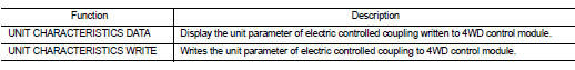
WORK SUPPORT
 System
4WD system : System Diagram
INPUT/OUTPUT SIGNAL
It transmits/receives each signal from the following 4WD control module via
CAN communication line.
4WD system : System Description
• 4WD mo ...
 ECU diagnosis information
4WD control module
Reference Value
VALUES ON THE DIAGNOSIS TOOL
TERMINAL LAYOUT
PHYSICAL VALUES
*: The values are changed by throttle opening and engine speed.
CAUTION:
When using ...
Other materials:
Parking brake switch
Component Function Check
1.CHECK PARKING BRAKE SWITCH OPERATION
Operate the parking brake lever. Then check that the brake warning lamp in
the combination meter turns ON/
OFF correctly.
Is the inspection result normal?
YES >> INSPECTION END
NO >> Proceed to BRC-208, "Diagn ...
On board diagnostic (OBD) system
Description
This is an onboard diagnosis system which records diagnosis information
related to the exhaust gases. It
detects malfunctions related to sensors and actuators. The malfunctions are
indicated by means of the malfunction
indicator lamp (MIL) and are stored as DTC in the ECU memory. ...
Interior room lamp control system
Wiring Diagram
For connector terminal arrangements, harness layouts, and alphabets in a
(option abbreviation: if not
described in wiring diagram), refer to GI-12, "Connector Information/Explanation
of Option Abbreviation".
...