Nissan Juke Service and Repair Manual : Cooler pipe and hose
Exploded View

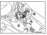
1. A/C unit assembly
2. O-ring
3. High-pressure pipe
4. Condenser
5. Low-pressure flexible hose
6. O-ring
7. Compressor
8. O-ring
9. High-pressure flexible hose
 : Do not reuse
 : N·m (kg-m, in-lb)
 : N·m (kg-m, ft-lb)
High-pressure flexible hose : Removal and Installation
CAUTION:
Perform lubricant return operation before each refrigeration system disassembly.
However, if a large
amount of refrigerant or lubricant is detected, never perform lubricant return
operation. Refer to HA-
23, "Perform Lubricant Return Operation
".
REMOVAL
1. Use a refrigerant collecting equipment (for HFC-134a) to discharge the refrigerant. Refer to HA-21, "Recycle Refrigerant".
2. Remove mounting bolt (A), and then disconnect high-pressure flexible hose from condenser.
CAUTION:
Cap or wrap the joint of the A/C piping and condenser with
suitable material such as vinyl tape to avoid the entry of air.

3. Remove mounting bolt (A), and then disconnect high-pressure flexible hose from compressor.
CAUTION:
Cap or wrap the joint of the A/C piping and compressor with
suitable material such as vinyl tape to avoid the entry of air.

4. Remove high-pressure flexible hose from vehicle.
INSTALLATION
Note the following items, and then install in the reverse order of removal.
CAUTION:
• Replace O-rings with new ones. Then apply compressor oil to them when
installing.
• Check for leakages when recharging refrigerant. Refer to HA-19, "Leak Test".
Low-pressure flexible hose : Removal and Installation
CAUTION:
Perform lubricant return operation before each refrigeration system disassembly.
However, if a large
amount of refrigerant or lubricant is detected, never perform lubricant return
operation. Refer to HA-
23, "Perform Lubricant Return Operation".
REMOVAL
1. Use a refrigerant collecting equipment (for HFC-134a) to discharge the refrigerant. Refer to HA-21, "Recycle Refrigerant".
2. Remove air duct. Refer to EM-161, "Removal and Installation".
3. Remove low-pressure flexible hose (1) mounting bolt (A), and nut (B).

4. Remove plastic nut, and then move lower dash insulator aside.
 : Plastic nut

5. Remove mounting bolt (A), and then disconnect low-pressure flexible hose (1) and high-pressure pipe (2) from expansion valve. Refer to HA-56, "EXPANSION VALVE : Removal and Installation".
CAUTION:
Cap or wrap the joint of the A/C piping and expansion valve
with suitable material such as vinyl tape to avoid the entry
of air.
6. Remove mounting bolt (A), and then remove low-pressure flexible hose (1) from compressor.
CAUTION:
Cap or wrap the joint of the A/C piping and compressor with
suitable material such as vinyl tape to avoid the entry of air.

INSTALLATION
Note the following items, and then install in the reverse order of removal.
CAUTION:
• Replace O-rings with new ones. Then apply compressor oil to them when
installing.
• Check for leakages when recharging refrigerant. Refer to HA-19, "Leak Test".
High-pressure pipe : Removal and Installation
CAUTION:
Perform lubricant return operation before each refrigeration system disassembly.
However, if a large
amount of refrigerant or lubricant is detected, never perform lubricant return
operation. Refer to HA-
23, "Perform Lubricant Return Operation".
REMOVAL
1. Use a refrigerant collecting equipment (for HFC-134a) to discharge the refrigerant. Refer to HA-21, "Recycle Refrigerant".
2. Remove air duct. Refer to EM-161, "Removal and Installation".
3. Remove low-pressure flexible hose (1) mounting bolt (A), and nut (B).

4. Remove plastic nut, and then move lower dash insulator aside.
 : Plastic nut

5. Remove mounting bolt (A), and then disconnect low-pressure flexible hose (1) and high-pressure pipe (2) from expansion valve. Refer to HA-56, "EXPANSION VALVE : Removal and Installation".
CAUTION:
Cap or wrap the joint of the A/C piping and expansion valve
with suitable material such as vinyl tape to avoid the entry
of air.

6. Remove mounting bolt (A), and then disconnect high-pressure pipe from condenser.
CAUTION:
Cap or wrap the joint of the A/C piping and condenser with
suitable material such as vinyl tape to avoid the entry of air.

7. Remove mounting bolt (A), and then remove ground wire (1) from engine unit.
8. Remove high-pressure pipe (2) fixing clips (B), and then remove high-pressure pipe.

INSTALLATION
Note the following items, and then install in the reverse order of removal.
CAUTION:
• Replace O-rings with new ones. Then apply compressor oil to them when
installing.
• Check for leakages when recharging refrigerant. Refer to HA-19, "Leak Test".
 Compressor
Exploded View
REMOVAL
1. High-pressure flexible hose
2. O-ring
3. Compressor
4. O-ring
5. Low-pressure flexible hose
A. To condenser
B. To evaporator
: N·m (kg-m, ft-lb)
DISASSEMBLY
...
 Condenser
Exploded View
1. Condenser
2. Refrigerant pressure sensor
3. O-ring
4. Grommet
5. Braket
6. O-ring
7. Liquid tank braket
8. Liquid tank
: Do not reuse
: N·m (kg-m, in-lb)
: N·m (kg-m ...
Other materials:
Precaution
Precaution for Supplemental Restraint System (SRS) "AIR BAG" and "SEAT
BELT
PRE-TENSIONER"
The Supplemental Restraint System such as “AIR BAG” and “SEAT BELT PRE-TENSIONER”,
used along
with a front seat belt, helps to reduce the risk or severity of injury to the
driver a ...
Foreword
Welcome to the growing family of new NISSAN owners. This vehicle is delivered
to you with confidence. It was produced using the latest techniques and strict quality
control.
This manual was prepared to help you understand the operation and maintenance
of your vehicle so that you may enjoy man ...
Side oil seal
Removal and Installation
REMOVAL
1. Remove front drive shafts. (MR16DDT) Refer to FAX-22, "LEFT SIDE : Removal
and Installation" (LEFT
SIDE) and FAX-24, "RIGHT SIDE : Removal and Installation" (RIGHT SIDE).
2. Remove front drive shafts. (K9K) Refer to FAX-78, "LEFT SID ...