Nissan Juke Service and Repair Manual : Center console assembly
Exploded View
CVT models

1. Console indicator finisher
2. Instrument lower cover RH
3. Center console assembly
4. Instrument lower cover LH
5. Instrument stay
6. CVT shift selector assembly
7. Console rear bracket
8. Console rear finisher
9. Seat heated switch
10. Console switch finisher
11. Console switch finisher
12. Console finisher assembly
13. Console mask
14. Console front bracket
 : Pawl
 : Metal clip
MT model

1. Console boot
2. Instrument lower cover RH
3. Center console assembly
4. Instrument lower cover LH
5. Instrument stay
6. Console center bracket
7. Console rear bracket
8. Console rear finisher
9. Seat heated switch
10. Console switch finisher
11. Console switch finisher
12. Console finisher assembly
13. Console mask
14. Console front bracket
 : Pawl
 : Metal clip
Removal and Installation
WARNING:
Before servicing, turn ignition switch OFF, disconnect battery negative terminal
and wait 3 minutes or
more.
REMOVAL
CAUTION:
When removing, always use a remover tool that is made of plastic.
1. Remove shift lever knob (MT models only).
• 5MT models: Refer to TM-25, "Removal and Installation".
• 6MT models: Refer to TM-78, "Removal and Installation".
2. Remove console finisher assembly.
1. Put selector lever in “N” position.
2. Loosen the parking brake lever stroke by turning the adjusting nut with a socket wrench. Refer to PB- 2, "Inspection and Adjustment".
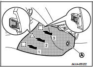
3. Lift up console finisher assembly in numerical order shown in the figure and disengage metal clips.
4. Remove console finisher assembly while pulling it towards vehicle rear.

 : Metal clip
CAUTION:
• Be careful not for damaging parts in surrounding area.
• Remove metal clips slowly so that they are not damaged.
3. Remove console rear finisher.
1. Put front seat assembly (LH and RH) to frontmost position.
2. Pull back console rear finisher, and disengage the pawls and metal clips.
 : Pawl
 : Metal clip

4. Remove center console assembly fixing screws (A).

5. Remove instrument lower cover LH.
1. Put front seat assembly LH to rearmost position.
2. Remove fixing clip (A).
3. Pull the instrument lower cover LH crosswise, and disengage the pawl and metal clips.
CAUTION:
Remove pawl and metal clips slowly so that they are not
damaged.
 : Pawl
 : Metal clip

6. Remove instrument lower cover RH.
1. Put front seat assembly RH to rearmost position.
2. Remove fixing clip (A).
3. Pull the instrument lower cover RH crosswise, and disengage the pawl and metal clips.
CAUTION:
Remove pawl and metal clips slowly so that they are not
damaged.
 : Pawl
 : Metal clip
7. Remove center console assembly.

1. Remove center console fixing screws (A).
2. Lift up center console assembly back side.
CAUTION:
Be careful not for damaging parts in surrounding area.
INSTALLATION
Note the following item, and then install in the reverse order of removal.
CAUTION:
After installation, adjust the parking brake lever stroke. Refer to PB-2,
"Inspection and Adjustment".
Disassembly and Assembly
Disassembly and Assembly of Console Finisher Assembly
CAUTION
:
When disassembling, always use a remover tool that is made of plasti
c.
DISASSEMBLY
1. Remove console finisher assembly. Refer to IP-23, "Removal and Installation".
2. Remove console indicator finisher (CVT models)
Disengage connection of the console indicator finisher (2) fixing pawls from the inside of the console finisher assembly (1) toward the outside, and remove.
 : Pawl

3. Remove console indicator finisher (MT models)
Disengage connection of the console boot (2) fixing pawls from the inside of the console finisher assembly (1) toward the outside, and remove.
 : Pawl

4. Remove console switch finisher.
Disengage connection of the console switch finisher (2) fixing pawls from the inside of the console finisher assembly (1) toward the outside, and remove.
NOTE
:
Remove seat heated switch. Refer to SE-51, "Removal and
Installation".
 : Pawl

ASSEMBLY
Assemble in the reverse order of disassembly.
 Instrument panel assembly
Exploded View
LHD models
1. Front passenger air bag module
2. Instrument panel assembly
3. Instrument side finisher LH
4. Combination meter
5. Cluster lid A
6. Push-button ignition switch ...
 Seat
Seat
...
Other materials:
Vehicle Dynamic Control (VDC) system
The Vehicle Dynamic Control (VDC) system uses various sensors to monitor driver
inputs and vehicle motion. Under certain driving conditions, the VDC system helps
to perform the following functions.
• Controls brake pressure to reduce wheel slip on one slipping drive wheel so
power is transfer ...
Power supply and ground circuit
Diagnosis Procedure
1.CHECK FUSE AND FUSIBLE LINK
Check that the following fuse and fusible link are not blown.
Is the fuse fusing?
YES >> Replace the blown fuse or fusible link after repairing the affected
circuit if a fuse or fusible link is
blown.
NO >> GO TO 2.
2.CHECK ...
P0638 electric throttle control actuator function
DTC Logic
DTC DETECTION LOGIC
NOTE:
If DTC P0638 is displayed with DTC P0120 or P2100, first perform trouble
diagnosis for DTC P0120 or P2100.
Refer to EC-909, "DTC Logic" (P0120), EC-997, "DTC Logic" (P2100).
Diagnosis Procedure
1.CHECK ELECTRIC THROTTLE CONTROL ACTU ...