Nissan Juke Service and Repair Manual : Brake piping
Front : Exploded View
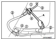
WITHOUT ESP

1. Brake booster
2. Master cylinder assembly
3. Brake tube
4. Connector bracket
5. Connector
6. ABS actuator and electric unit (control
unit)
7. Lock plate
8. Brake hose
9. Union bolt
10. Copper washer
A. To rear brake tube
 : N·m (kg-m, ft-lb)
 : N·m (kg-m, in-lb)
 : Always replace after every
disassembly.
WITH ESP
MR16DDT

1. Brake booster
2. Master cylinder assembly
3. Brake tube
4. Connector bracket
5. Connector
6. ABS actuator and electric unit (control
unit)
7. Lock plate
8. Brake hose
9. Union bolt
10. Copper washer
A. To rear brake tube
: N·m (kg-m, ft-lb)
: N·m (kg-m, in-lb)
: Always replace after every
disassembly.
HR16DE

1. Brake booster
2. Master cylinder assembly
3. Brake tube
4. Connector bracket
5. Connector
6. ABS actuator and electric unit (control
unit)
7. Lock plate
8. Brake hose
9. Union bolt
10. Copper washer
A. To rear brake tube
: N·m (kg-m, ft-lb)
: N·m (kg-m, in-lb)
: Always replace after every
disassembly.
K9K

1. Brake booster
2. Master cylinder assembly
3. Brake tube
4. Connector bracket
5. Connector
6. ABS actuator and electric unit (control
unit)
7. Lock plate
8. Brake hose
9. Union bolt
10. Copper washer
A. To rear brake tube
: N·m (kg-m, ft-lb)
: N·m (kg-m, in-lb)
: Always replace after every
disassembly.
Front : Hydraulic Piping
2WD

1. Brake booster
2. Master cylinder assembly
3. Front disc brake
4. ABS actuator and electric unit (control
unit)
5. Connector
6. Rear disc brake
A. Brake tube
B. Brake hose
 : Flare nut
 : Union bolt
4WD

1. Brake booster
2. Master cylinder assembly
3. Front disc brake
4. ABS actuator and electric unit (control
unit)
5. Connector
6. Rear disc brake
A. Brake tube
B. Brake hose
: Flare nut
: Union bolt
Front : Removal and Installation
REMOVAL
CAUTION:
• Never spill or splash brake fluid on painted surfaces. Brake fluid may
seriously damage paint. Wipe it
off immediately and wash with water if it gets on a painted surface. For brake
component parts,
never wash them with water.
• Never depress the brake pedal while removing the brake hose or brake tube. If this is not complied with, brake fluid may splash.
1. Remove tires.
2. Drain brake fluid. Refer to BR-80, "Draining".
3. Loosen the flare nut (1) with a flare nut wrench (A) and separate the brake tube (2) from the brake hose (3).
CAUTION:
• Never scratch the flare nut and the brake tube.
• Never bend sharply, twist or strongly pull out the brake hoses and tubes.
• Cover open end of brake tubes and hoses when disconnecting to prevent entrance of dirt.

4. Remove the union bolt (1) and copper washers (2), and remove the brake hose (3) from the brake caliper assembly.
5. Remove the lock plate (4) and remove the brake hose.

INSTALLATION
CAUTION:
• Never spill or splash brake fluid on painted surfaces. Brake fluid may
seriously damage paint. Wipe it
off immediately and wash with water if it gets on a painted surface. For brake
component parts,
never wash them with water.
• Never depress the brake pedal while removing the brake hose or brake tube. If this is not complied with, brake fluid may splash.
1. Assemble the union bolt (1) and the copper washer (2) to the brake hose.
CAUTION:
Never reuse the copper washe
r.
2. Align the brake hose pin (A) with the brake caliper assembly projection (B), and tighten the union bolt (1) to the specified torqu

3. Install the brake tube (2) to the brake hose (1), temporarily tighten the flare nut (3) by hand until it does not rotate further, and fix the brake hose to the bracket (5) with the lock plate (4).
CAUTION:
Check that all brake hoses and brake tubes are not twisted
and bent.

4. Tighten the flare nut to the specified torque with a flare nut torque wrench (A).
CAUTION:
Never scratch the flare nut and the brake tube.
5. Refill with new brake fluid and perform the air bleeding. Refer to BR-81, "Bleeding Brake System".
CAUTION:
Never reuse drained brake fluid.
6. Install tires. Refer to WT-7, "Exploded View".
7. Perform inspection after installation. Refer to BR-97, "FRONT : Inspection".

Front : Inspection
INSPECTION AFTER INSTALLATION
1. Check the brake hoses and tubes for the following: no scratches; no twist and deformation; no interference with other components when steering the steering wheel; no looseness at connections.
2. Depress the brake pedal with a force of 785 N (80 kg, 176 lb) and hold down the pedal for approximately 5 seconds with the engine running. Check for any fluid leakage.
CAUTION:
Retighten the applicable connection to the specified torque and repair any
abnormal (damaged,
worn or deformed) part if any brake fluid leakage is present.
Rear : Exploded View
2WD (MR16DDT, HR16DE)

1. Brake tube
2. Brake hose A
3. Lock plate
4. Brake hose bracket
5. Union bolt
6. Brake hose B
7. Copper washer
A. To connector
 : N·m (kg-m, ft-lb)
 N·m (kg-m, in-lb)
 : Always replace after every
disassembly.
2WD (K9K)

1. Brake tube
2. Brake hose A
3. Lock plate
4. Brake hose bracket
5. Union bolt
6. Brake hose B
7. Copper washer
A. To connector
: N·m (kg-m, ft-lb)
: N·m (kg-m, in-lb)
: Always replace after every
disassembly.
4WD

1. Brake tube
2. Brake hose A
3. Lock plate
4. Brake hose bracket
5. Brake hose B
6. Union bolt
7. Copper washer
A. To connector
: N·m (kg-m, ft-lb)
: N·m (kg-m, in-lb)
: Always replace after every
disassembly.
Rear : Hydraulic Piping
2WD

1. Brake booster
2. Master cylinder assembly
3. Front disc brake
4. ABS actuator and electric unit (control
unit)
5. Connector
6. Rear disc brake
A. Brake tube
B. Brake hose
 : Flare nut
 : Union bolt
4WD

1. Brake booster
2. Master cylinder assembly
3. Front disc brake
4. ABS actuator and electric unit (control
unit)
5. Connector
6. Rear disc brake
A. Brake tube
B. Brake hose
 : Flare nut
 : Union bolt
Rear : Removal and Installation
REMOVAL
2WD
CAUTION:
• Never spill or splash brake fluid on painted surfaces. Brake fluid may
seriously damage paint. Wipe it
off immediately and wash with water if it gets on a painted surface. For brake
component parts,
never wash them with water.
• Never depress the brake pedal while removing the brake hose or brake tube. If this is not complied with, brake fluid may splash.
1. Remove tires.
2. Drain brake fluid. Refer to BR-80, "Draining".
3. Loosen the flare nut (1) with a flare nut wrench (A) and separate the brake tube (2) from the brake hose A (3).
CAUTION:
• Never scratch the flare nut and the brake tube.
• Never bend sharply, twist or strongly pull out the brake hoses and tubes.
• Cover open end of brake tubes and hoses when disconnecting to prevent entrance of dirt
.
4. Remove the lock plate (4) and remove the brake hose A.

5. Loosen the flare nut (1) with a flare nut wrench (A) and separate the brake tube (2) from the hose B (3).
CAUTION:
• Never scratch the flare nut and the brake tube.
• Never bend sharply, twist or strongly pull out the brake hoses and tubes.
• Cover open end of brake tubes and hoses when disconnecting to prevent entrance of dirt
.
6. Remove the lock plate (4) from brake hose bracket (5).

7. Remove the union bolt (1) and copper washers (2), and remove the brake hose B (3) from the brake caliper assembly.

4WD
CAUTION:
• Never spill or splash brake fluid on painted surfaces. Brake fluid may
seriously damage paint. Wipe it
off immediately and wash with water if it gets on a painted surface. For brake
component parts,
never wash them with water.
• Never depress the brake pedal while removing the brake hose or brake tube. If this is not complied with, brake fluid may splash.
1. Remove tires.
2. Drain brake fluid. Refer to BR-80, "Draining".
3. Loosen the flare nut (1) with a flare nut wrench (A) and separate the brake tube (2) from the hose A (3).
CAUTION:
• Never scratch the flare nut and the brake tube.
• Never bend sharply, twist or strongly pull out the brake hoses and tubes.
• Cover open end of brake tubes and hoses when disconnecting to prevent entrance of dirt.
4. Remove the lock plate (4) and remove the brake hose A.
5. Loosen the flare nut (1) with a flare nut wrench (A) and separate the brake tube (2) from the hose B (3).
CAUTION:
• Never scratch the flare nut and the brake tube.
• Never bend sharply, twist or strongly pull out the brake hoses and tubes.
• Cover open end of brake tubes and hoses when disconnecting to prevent entrance of dirt.
6. Remove the lock plate (4) from brake hose bracket (5).

7. Remove the union bolt (1) and copper washers (2), and remove the brake hose B (3) from the brake caliper assembly.

INSTALLATION
2WD
CAUTION:
• Never spill or splash brake fluid on painted surfaces. Brake fluid may
seriously damage paint. Wipe it
off immediately and wash with water if it gets on a painted surface. For brake
component parts,
never wash them with water.
• Never depress the brake pedal while removing the brake hose or brake tube. If this is not complied with, brake fluid may splash.
1. Assemble the union bolt (1) and the copper washer (2) to the brake hose B.
CAUTION:
Never reuse the copper washer.
2. Align the brake hose B L-pin (A) with the brake caliper assembly hole (B), and tighten the union bolt (1) to the specified torque.

3. Install the brake tube (2) to the brake hose B (1), temporarily tighten the flare nut (3) by hand until it does not rotate further, and fix the brake hose B to the brake hose bracket (5) with the lock plate (4).
CAUTION:
Check that all brake hoses and brake tubes are not twisted
and bent.

4. Tighten the flare nut to the specified torque with a flare nut torque wrench (A).
CAUTION:
Never scratch the flare nut and the brake tube.

5. Install the brake tube (2) to the brake hose A (1), temporarily tighten the flare nut (3) by hand until it does not rotate further, and fix the brake hose with the lock plate (4).
CAUTION:
Check that all brake hoses and brake tubes are not twisted
and bent.

6. Tighten the flare nut to the specified torque with a flare nut torque wrench (A).
CAUTION:
Never scratch the flare nut and the brake tube.
7. Refill with new brake fluid and perform the air bleeding. Refer to BR-81, "Bleeding Brake System".
CAUTION:
Never reuse drained brake fluid.
8. Install tires. Refer to WT-7, "Exploded View".
9. Perform inspection after installation. Refer to BR-105, "REAR : Inspection".

4WD
CAUTION:
• Never spill or splash brake fluid on painted surfaces. Brake fluid may
seriously damage paint. Wipe it
off immediately and wash with water if it gets on a painted surface. For brake
component parts,
never wash them with water.
• Never depress the brake pedal while removing the brake hose or brake tube. If this is not complied with, brake fluid may splash.
1. Assemble the union bolt (1) and the copper washer (2) to the brake hose B.
CAUTION:
Never reuse the copper washer.
2. Align the brake hose B L-pin (A) with the brake caliper assembly hole (B), and tighten the union bolt (1) to the specified torque.

3. Install the brake tube (2) to the brake hose B (1), temporarily tighten the flare nut (3) by hand until it does not rotate further, and fix the brake hose B to the brake hose bracket (5) with the lock plate (4).
CAUTION:
Check that all brake hoses and brake tubes are not twisted
and bent.

4. Tighten the flare nut to the specified torque with a flare nut torque wrench (A).
CAUTION:
Never scratch the flare nut and the brake tube.

5. Install the brake tube (2) to the brake hose A (3), temporarily tighten the flare nut (1) by hand until it does not rotate further, and fix the brake hose A to the bracket with the lock plate (4).
CAUTION:
Check that all brake hoses and brake tubes are not twisted
and bent.

6. Tighten the flare nut to the specified torque with a flare nut torque wrench (A).
CAUTION:
Never scratch the flare nut and the brake tube.
7. Refill with new brake fluid and perform the air bleeding. Refer to BR-81, "Bleeding Brake System".
CAUTION:
Never reuse drained brake fluid.
8. Install tires. Refer to WT-7, "Exploded View".
9. Perform inspection after installation. Refer to BR-105, "REAR : Inspection".

Rear : Inspection
INSPECTION AFTER INSTALLATION
1. Check the brake hoses and tubes for the following: no scratches; no twist and deformation; no looseness at connections.
2. Depress the brake pedal with a force of 785 N (80kg, 176 lb) and hold down the pedal for approximately 5 seconds with the engine running. Check for any fluid leakage.
CAUTION
:
Retighten the applicable connection to the specified torque and repair any
abnormal (damaged,
worn or deformed) part if any brake fluid leakage is present.
 Brake pedal
Exploded View
WITHOUT ESP
1. Clevis pin
2. Brake pedal assembly
3. Brake pedal pad
4. Stop lamp switch
5. Clip
6. Snap pin
: Apply multi-purpose grease.
: N·m (kg-m, ft-lb)
WITH ESP
...
 Brake master cylinder
Exploded View
2WD
1. Reservoir cap
2. Oil strainer
3. Reservoir tank
4. Cylinder body
5. O-ring
6. Grommet
7. Pin
: Apply polyglycol ether
lubricant
: Apply brake fluid.
: N·m (kg-m ...
Other materials:
Component parts
Charging system
CHARGING SYSTEM : Component Parts Location
1. Charge warning lamp (On the combination
meter)
2. Alternat
CHARGING SYSTEM : Component Description
Power generation voltage variable control system
POWER GENERATION VOLTAGE VARIABLE CONTROL SYSTEM : Component
Parts Location
N ...
P0222, P0223 TP sensor
DTC Logic
DTC DETECTION LOGIC
NOTE:
If DTC P0222 or P0223 is displayed with DTC P0643 ,first perform the trouble
diagnosis for DTC P0643.
Refer to EC-274, "DTC Logic".
DTC CONFIRMATION PROCEDURE
1.PRECONDITIONING
If DTC Confirmation Procedure has been previously conducted, alw ...
LAN System can system (type 5)
DTC/CIRCUIT DIAGNOSIS
Main line between IPDM-E and DLC circuit
Diagnosis Procedure
1.CHECK CONNECTOR
1. Turn the ignition switch OFF.
2. Disconnect the battery cable from the negative terminal.
3. Check the following terminals and connectors for damage, bend and loose
connection (connector s ...