Nissan Juke Service and Repair Manual : Back door opener switch
Component Function Check
1.CHECK FUNCTION
1. Select “TRUNK” of “BCM” using CONSULT-III.
2. Select “TRNK OPNR SW” in “DATA MONITOR” mode.
3. Check that the function operates normally according to the following conditions.
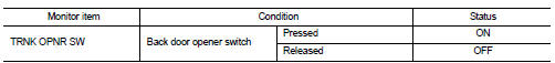
Is the inspection result normal? YES >> Back door opener switch is OK.
NO >> Refer to DLK-513, "Diagnosis Procedure".
Diagnosis Procedure
1.CHECK BACK DOOR OPEN INPUT SIGNAL
1. Turn ignition switch OFF.
2. Disconnect back door opener switch connector.
3. Check signal between back door opener switch harness connector and ground using oscilloscope.
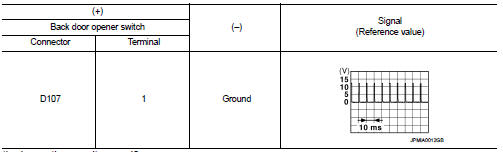
Is the inspection result normal? YES >> GO TO 3.
NO >> GO TO 2.
2.CHECK BACK DOOR OPENER SWITCH CIRCUIT
1. Disconnect BCM connector.
2. Check continuity between BCM harness connector and back door opener switch harness connector.

3. Check continuity between BCM harness connector and ground.

Is the inspection result normal? YES >> Replace BCM. Refer to BCS-161, "Removal and Installation".
NO >> Repair or replace harness.
3.CHECK BACK DOOR OPENER SWITCH GROUND CIRCUIT
Check continuity between back door opener switch harness connector and ground.

Is the inspection result normal? YES >> GO TO 4.
NO >> Repair or replace harness.
4.CHECK BACK DOOR OPENER SWITCH
Refer to DLK-514, "Component Inspection".
Is the inspection result normal? YES >> GO TO 5.
NO >> Replace back door opener switch.
5.CHECK INTERMITTENT INCIDENT
Refer to GI-42, "Intermittent Incident".
>> INSPECTION END
Component Inspection
1.CHECK BACK DOOR OPENER SWITCH
1. Turn ignition switch OFF.
2. Disconnect back door opener switch connector.
3. Check continuity between back door opener switch terminals.

Is the inspection result normal? YES >> INSPECTION END
NO >> Replace back door opener switch.
 Back door opener actuator
Diagnosis Procedure
1.CHECK BACK DOOR OPENER ACTUATOR INPUT SIGNAL
1. Turn ignition switch OFF.
2. Disconnect back door opener assembly connector.
3. Check voltage between back door opener assembl ...
 Door lock actuator
Driver side
DRIVER SIDE : Component Function Check
1.CHECK FUNCTION
1. Select “DOOR LOCK” of “BCM” using CONSULT-III.
2. Select “DOOR LOCK” in “ACTIVE TEST” mode.
3. Check that the function opera ...
Other materials:
Periodic maintenance
REAR PROPELLER SHAFT
Inspection
APPEARANCE AND NOISE
• Check the propeller shaft tube surface for dents or cracks. If damaged,
replace propeller shaft assembly.
• If center bearing is noisy or damaged, replace propeller shaft assembly.
VIBRATION
If vibration is present at high speed, inspe ...
Keyfob battery
Component Function Check
1.CHECK FUNCTION
Check door lock and unlock operation with keyfob button.
Is the inspection result normal?
YES >> Keyfob is OK.
NO >> Refer to DLK-528, "Diagnosis Procedure".
Diagnosis Procedure
1.CHECK KEYFOB BATTERY
Check by connecting a r ...
Headlamp washer relay
Component Inspection
1.CHECK HEADLAMP WASHER RELAY
1. Turn the ignition switch OFF.
2. Remove headlamp washer relay.
3. Apply battery voltage to headlamp washer relay between terminals 1 and 2.
4. Check continuity of headlamp washer relay.
Is the inspection result normal?
YES >> Headl ...