Nissan Juke Service and Repair Manual : B26F5 steering lock status switch
DTC Logic
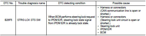
DTC DETECTION LOGIC
NOTE
:
• If DTC B26F5 is displayed with DTC U1000, first perform the trouble diagnosis
for DTC U1000. Refer to
BCS-83, "DTC Logic".
• If DTC B26F5 is displayed with DTC U1010, first perform the trouble diagnosis for DTC U1010. Refer to BCS-84, "DTC Logic".
DTC CONFIRMATION PROCEDURE
1.PERFORM DTC CONFIRMATION PROCEDURE
1. Shift selector lever to the P position.
2. Turn ignition switch ON.
3. Turn ignition switch OFF.
4. Press driver side door switch.
5. Check DTC in “Self Diagnostic Result” mode of “BCM” using CONSULT-III.
Is DTC detected? YES >> Go to SEC-123, "Diagnosis Procedure".
NO >> INSPECTION END
Diagnosis Procedure
1.CHECK IPDM E/R INPUT SIGNAL
1. Turn ignition switch OFF.
2. Check voltage between IPDM E/R harness connector and ground.

NOTE:

Is the inspection result normal? YES >> GO TO 4.
NO >> GO TO 2.
2.CHECK IPDM E/R INPUT SIGNAL CIRCUIT
1. Disconnect IPDM E/R connector and steering lock unit connector.
2. Check continuity between IPDM E/R harness connector and steering lock unit harness connector.

3. Check continuity between IPDM E/R harness connector and ground.

Is the inspection result normal? YES >> GO TO 3.
NO >> Repair or replace harness.
3.REPLACE STEERING LOCK UNIT
1. Replace steering lock unit.
2. Perform the service procedure for steering lock unit replacement. Refer to CONSULT-III Operation Manual NATS-IVIS/NVIS.
>> INSPECTION END
4.CHECK BCM INPUT SIGNAL
1. Turn ignition switch OFF.
2. Check voltage between BCM harness connector and ground.

NOTE:

Is the inspection result normal? YES >> GO TO 5.
NO >> GO TO 6.
5.REPLACE BCM
1. Replace BCM. Refer to BCS-93, "Removal and Installation".
2. Perform initialization of BCM and registration of all Intelligent Keys using CONSULT-III.
For initialization and registration procedures, refer to CONSULT-III Operation Manual NATS-IVIS/NVIS.
>> INSPECTION END
6.CHECK BCM INPUT SIGNAL CIRCUIT
1. Disconnect BCM connector and steering lock unit connector.
2. Check continuity between BCM harness connector and steering lock unit harness connector.

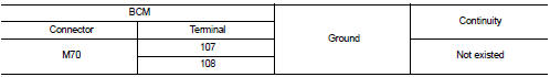
3. Check continuity between BCM harness connector and ground.
Is the inspection result normal? YES >> GO TO 7.
NO >> Repair or replace harness.
7.REPLACE STEERING LOCK UNIT
1. Replace steering lock unit.
2. Perform the service procedure for steering lock unit replacement. Refer to CONSULT-III Operation Manual NATS-IVIS/NVIS.
>> INSPECTION END
 B26F4 starter control relay
DTC Logic
DTC DETECTION LOGIC
NOTE:
• If DTC B26F4 is displayed with DTC U1000, first perform the trouble diagnosis
for DTC U1000. Refer to
BCS-83, "DTC Logic".
• If DTC B26F4 is disp ...
 B26F7 BCM
DTC Logic
DTC DETECTION LOGIC
DTC CONFIRMATION PROCEDURE
1.PERFORM DTC CONFIRMATION PROCEDURE
1. Press door request switch.
2. Turn ignition switch ON.
3. Check DTC in “Self Diagnostic Result” ...
Other materials:
Door motor
Diagnosis Procedure
NOTE:
If all of door motor DTCs are detected, check this circuit.
1.CHECK DOOR MOTOR POWER SUPPLY
1. Turn ignition switch ON.
2. Check voltage between intake door motor harness connector and ground.
Is the inspection result normal?
YES >> GO TO 2.
NO >> ...
B2099 ignition relay off stuck
Description
The ignition relay integrated in IPDM E/R is operated with ignition switch ON
signal from the ignition switch.
DTC Logic
DTC DETECTION LOGIC
NOTE:
When IPDM E/R power supply voltage is low (Approx. 7 - 8 V for about 1 second),
the “DTC: B2099” may be detected.
1.PERFORM DTC ...
Precaution Necessary for Steering Wheel Rotation after Battery Disconnect
NOTE:
• Before removing and installing any control units, first turn the ignition
switch to the LOCK position, then disconnect
both battery cables.
• After finishing work, confirm that all control unit connectors are connected
properly, then re-connect both
battery cables.
• Always use CONS ...