Nissan Juke Service and Repair Manual : B2612 steering status
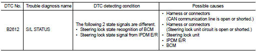
DTC Logic
DTC DETECTION LOGIC
NOTE
:
• If DTC B2612 is displayed with DTC U1000, first perform the trouble diagnosis
for DTC U1000. Refer to
BCS-83, "DTC Logic".
• If DTC B2612 is displayed with DTC U1010, first perform the trouble diagnosis for DTC U1010. Refer to BCS-84, "DTC Logic".
DTC CONFIRMATION PROCEDURE
1.PERFORM DTC CONFIRMATION PROCEDURE 1
1. Press push-button ignition switch under the following conditions and wait 1 second or more.
- Selector lever: In the P position - Brake pedal: Not depressed 2. Check DTC in “Self Diagnostic Result” mode of “BCM” using CONSULT-III.
Is DTC detected? YES >> Go to SEC-102, "Diagnosis Procedure".
NO >> GO TO 2.
2.PERFORM DTC CONFIRMATION PROCEDURE 2
1. Turn ignition switch ON.
2. Turn ignition switch OFF.
3. Press driver side door switch and wait 1 second or more.
4. Check DTC in “Self Diagnostic Result” mode of “BCM” using CONSULT-III.
Is DTC detected? YES >> Go to SEC-102, "Diagnosis Procedure".
NO >> INSPECTION END
Diagnosis Procedure
1.CHECK IPDM E/R INPUT SIGNAL
1. Turn ignition switch OFF.
2. Check voltage between IPDM E/R harness connector and ground.
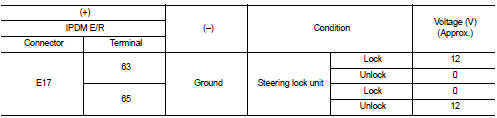
NOTE:

Is the inspection result normal? YES >> GO TO 4.
NO >> GO TO 2.
2.CHECK IPDM E/R INPUT SIGNAL CIRCUIT
1. Disconnect IPDM E/R connector and steering lock unit connector.
2. Check continuity between IPDM E/R harness connector and steering lock unit harness connector.

3. Check continuity between IPDM E/R harness connector and ground.

Is the inspection result normal? YES >> GO TO 3.
NO >> Repair or replace harness.
3.REPLACE STEERING LOCK UNIT
1. Replace steering lock unit.
2. Perform the service procedure for steering lock unit replacement. Refer to CONSULT-III Operation Manual NATS-IVIS/NVIS.
>> INSPECTION END
4.CHECK BCM INPUT SIGNAL
1. Turn ignition switch OFF.
2. Check voltage between BCM harness connector and ground.

NOTE:

Is the inspection result normal? YES >> GO TO 5.
NO >> GO TO 6.
5.REPLACE BCM
1. Replace BCM. Refer to BCS-93, "Removal and Installation".
2. Perform initialization of BCM and registration of all Intelligent Keys using CONSULT-III.
For initialization and registration procedures, refer to CONSULT-III Operation Manual NATS-IVIS/NVIS.
>> INSPECTION END
6.CHECK BCM INPUT SIGNAL CIRCUIT
1. Disconnect BCM connector and steering lock unit connector.
2. Check continuity between BCM harness connector and steering lock unit harness connector.

3. Check continuity between BCM harness connector and ground.

Is the inspection result normal? YES >> GO TO 7.
NO >> Repair or replace harness.
7.REPLACE STEERING LOCK UNIT
1. Replace steering lock unit.
2. Perform the service procedure for steering lock unit replacement. Refer to CONSULT-III Operation Manual NATS-IVIS/NVIS.
>> INSPECTION END
 B260F Engine status
Description
BCM receives the engine status signal from ECM via CAN communication.
DTC Logic
DTC DETECTION LOGIC
NOTE:
• If DTC B260F is displayed with DTC U1000, first perform the trouble diagnos ...
 B2619 BCM
DTC Logic
DTC DETECTION LOGIC
DTC CONFIRMATION PROCEDURE
1.PERFORM DTC CONFIRMATION PROCEDURE
1. Press push-button ignition switch under the following conditions and wait
1 second or more.
- ...
Other materials:
B1215, B1216, B1217 satellite sensor LH
DTC Logic
DTC DETECTION LOGIC
DTC CONFIRMATION PROCEDURE
1.CHECK SELF-DIAG RESULT
With CONSULT-III
1. Turn ignition switch ON.
2. Perform “Self Diagnostic Result” mode of “AIR BAG” using CONSULT-III.
Without CONSULT-III
1. Turn ignition switch ON.
2. Check the air bag warning lamp statu ...
Driving on snow or ice
WARNING
• Wet ice (328F, 08C and freezing rain), very cold snow or ice can be slick
and very hard to drive on. The vehicle will have much less traction or “grip” under
these conditions. Try to avoid driving on wet ice until the road is salted or sanded.
• Whatever the condition, drive with cau ...
C1130 engine signal
DTC Logic
DTC DETECTION LOGIC
DTC CONFIRMATION PROCEDURE
1.PRECONDITIONING
If “DTC CONFIRMATION PROCEDURE” has been previously conducted, always turn
ignition switch OFF and
wait at least 10 seconds before conducting the next test.
>> GO TO 2.
2.CHECK DTC DETECTION
With CONSULT ...