Nissan Juke Service and Repair Manual : B2609 steering status
DTC Logic
DTC DETECTION LOGIC

DTC CONFIRMATION PROCEDURE
1.PERFORM DTC CONFIRMATION PROCEDURE 1
1. Press push-button ignition switch under the following conditions and wait 1 second or more.
- Selector lever: In the P position - Brake pedal: Not depressed 2. Check DTC in “Self Diagnostic Result” mode of “BCM” using CONSULT-III.
Is DTC detected? YES >> Go to SEC-95, "Diagnosis Procedure".
NO >> GO TO 2.
2.PERFORM DTC CONFIRMATION PROCEDURE 2
1. Turn ignition switch ON.
2. Turn ignition switch OFF.
3. Press driver side door switch and wait 1 second or more.
4. Check DTC in “Self Diagnostic Result” mode of “BCM” using CONSULT-III.
Is DTC detected? YES >> Go to SEC-95, "Diagnosis Procedure".
NO >> INSPECTION END
Diagnosis Procedure
1.CHECK IPDM E/R INPUT SIGNAL
1. Turn ignition switch OFF.
2. Check voltage between IPDM E/R harness connector and ground.
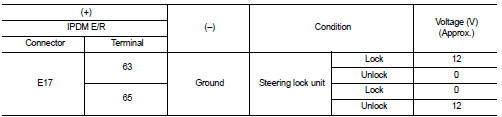
NOTE:

Is the inspection result normal? YES >> GO TO 4.
NO >> GO TO 2.
2.CHECK IPDM E/R INPUT SIGNAL CIRCUIT
1. Disconnect IPDM E/R connector and steering lock unit connector.
2. Check continuity between IPDM E/R harness connector and steering lock unit harness connector.

3. Check continuity between IPDM E/R harness connector and ground.

Is the inspection result normal? YES >> GO TO 3.
NO >> Repair or replace harness.
3.REPLACE STEERING LOCK UNIT
1. Replace steering lock unit.
2. Perform the service procedure for steering lock unit replacement. Refer to CONSULT-III Operation Manual NATS-IVIS/NVIS.
>> INSPECTION END
4.CHECK BCM INPUT SIGNAL
1. Turn ignition switch OFF.
2. Check voltage between BCM harness connector and ground.

NOTE:

Is the inspection result normal? YES >> GO TO 5.
NO >> GO TO 6.
5.REPLACE BCM
1. Replace BCM. Refer to BCS-93, "Removal and Installation".
2. Perform initialization of BCM and registration of all Intelligent Keys using CONSULT-III.
For initialization and registration procedures, refer to CONSULT-III Operation Manual NATS-IVIS/NVIS.
>> INSPECTION END
6.CHECK BCM INPUT SIGNAL CIRCUIT
1. Disconnect BCM connector and steering lock unit connector.
2. Check continuity between BCM harness connector and steering lock unit harness connector.

3. Check continuity between BCM harness connector and ground.

Is the inspection result normal? YES >> GO TO 7.
NO >> Repair or replace harness.
7.REPLACE STEERING LOCK UNIT
1. Replace steering lock unit.
2. Perform the service procedure for steering lock unit replacement. Refer to CONSULT-III Operation Manual NATS-IVIS/NVIS.
>> INSPECTION END
 B2608 starter relay
DTC Logic
DTC DETECTION LOGIC
NOTE:
• If DTC B2608 is displayed with DTC U1000, first perform the trouble diagnosis
for DTC U1000. Refer to
BCS-83, "DTC Logic".
• If DTC B2608 is disp ...
 B260B steering lock unit
DTC Logic
DTC DETECTION LOGIC
DTC CONFIRMATION PROCEDURE
1.PERFORM DTC CONFIRMATION PROCEDURE
1. Turn ignition switch ON.
2. Turn ignition switch OFF.
3. Press driver side door switch.
4. Shi ...
Other materials:
P0420 three way catalyst function
DTC Logic
DTC DETECTION LOGIC
The ECM monitors the switching frequency ratio of air fuel ratio (A/F)
sensor 1 and heated oxygen sensor 2.
A three way catalyst (manifold) with high oxygen storage capacity
will indicate a low switching frequency of heated oxygen sensor 2.
As oxygen storage c ...
Service Equipment
RECOVERY/RECYCLING RECHARGING EQUIPMENT
Be certain to follow the manufacturer’s instructions for machine operation
and machine maintenance. Never
introduce any refrigerant other than that specified into the machine.
ELECTRICAL LEAK DETECTOR
Be certain to follow the manufacturer’s instruction ...
Back door request switch
Component Function Check
1.CHECK FUNCTION
1. Select “INTELLIGENT KEY” of “BCM” using CONSULT-III.
2. Select “REQ SW-BD/TR” in “DATA MONITOR” mode.
3. Check that the function operates normally according to the following
conditions.
Is the inspection result normal?
YES >> Back door req ...