Nissan Juke Service and Repair Manual : B2581, B2582 intake sensor
DTC Logic
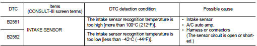
DTC DETECTION LOGIC
NOTE
:
• If DTC is displayed along with DTC U1000, first perform the trouble diagnosis
for DTC U1000. Refer to HAC-
51, "DTC Logic".
• If DTC is displayed along with DTC U1010, first perform the trouble diagnosis for DTC U1010. HAC-52, "DTC Logic".
DTC CONFIRMATION PROCEDURE
1.PERFORM DTC CONFIRMATION PROCEDURE
 With CONSULT-III
1. Turn ignition switch ON.
2. Select “Self Diagnostic Result” mode of “HVAC” using CONSULT-III.
3. Check DTC.
Is DTC detected? YES >> Refer to HAC-59, "Diagnosis Procedure".
NO >> INSPECTION END
Diagnosis Procedure
1.CHECK INTAKE SENSOR POWER SUPPLY
1. Turn ignition switch OFF.
2. Disconnect intake sensor connector.
3. Turn ignition switch ON.
4. Check voltage between intake sensor harness connector and ground.

Is the inspection result normal? YES >> GO TO 2.
NO >> GO TO 4.
2.CHECK INTAKE SENSOR GROUND CIRCUIT FOR OPEN
1. Turn ignition switch OFF.
2. Disconnect A/C auto amp. connector.
3. Check continuity between intake sensor harness connector and A/C auto amp harness connector.

Is the inspection result normal?
YES >> GO TO 3.
NO >> Repair harness or connector.
3.CHECK INTAKE SENSOR
Check intake sensor. Refer to HAC-57, "Component Inspection".
Is the inspection result normal? YES >> Replace A/C auto amp. Refer to HAC-91, "Removal and Installation".
NO >> Replace intake sensor. Refer to HAC-95, "Removal and Installation".
4.CHECK INTAKE SENSOR POWER SUPPLY CIRCUIT FOR OPEN
1. Turn ignition switch OFF.
2. Disconnect A/C auto amp. connector.
3. Check continuity between intake sensor harness connector and A/C auto amp. harness connector.

Is the inspection result normal? YES >> GO TO 5.
NO >> Repair harness or connector.
5.CHECK INTAKE SENSOR POWER SUPPLY CIRCUIT FOR SHORT
Check continuity between intake sensor harness connector and ground.

Is the inspection result normal? YES >> Replace A/C auto amp. Refer to HAC-91, "Removal and Installation".
NO >> Repair harness or connector.
Component Inspection
1.CHECK INTAKE SENSOR
1. Remove intake sensor. Refer to HAC-95, "Removal and Installation".
2. Check resistance between intake sensor terminals. Refer to applicable table for the normal value.

Is the inspection result normal? YES >> INSPECTION END
NO >> Replace intake sensor. Refer to HAC-95, "Removal and Installation".
 B257B, B257C ambient sensor
DTC Logic
DTC DETECTION LOGIC
NOTE:
• If DTC is displayed along with DTC U1000, first perform the trouble diagnosis
for DTC U1000. Refer to HAC-
51, "DTC Logic".
• If DTC is displayed ...
 B2630, B2631 sunload sensor
DTC Logic
DTC DETECTION LOGIC
NOTE:
• If DTC is displayed along with DTC U1000, first perform the trouble diagnosis
for DTC U1000. Refer to HAC-
51, "DTC Logic".
• If DTC is displayed ...
Other materials:
Precaution for Supplemental Restraint System (SRS) "AIR BAG" and "SEAT BELT
PRE-TENSIONER"
The Supplemental Restraint System such as “AIR BAG” and “SEAT BELT PRE-TENSIONER”,
used along
with a front seat belt, helps to reduce the risk or severity of injury to the
driver and front passenger for certain
types of collision. Information necessary to service the system safely is
include ...
P1616 ECM
DTC Logic
DTC DETECTION LOGIC
DTC CONFIRMATION PROCEDURE
1.PERFORM DTC CONFIRMATION PROCEDURE FOR MALFUNCTION
1. Turn ignition switch ON amd wait 2 seconds or more.
2. Check DTC in “Self Diagnostic Result” mode of “ENGINE” using CONSULT-III.
Is DTC detected?
YES >> Go to SEC-199, &q ...
Engine unit
Disassembly
1. Remove intake manifold. Refer to EM-28, "Exploded View".
2. Remove catalyst convertor. Refer to EM-33, "2WD : Exploded View" (2WD models)
or EM-34, "4WD :
Exploded View" (4WD models).
3. Remove turbocharger. Refer to EM-36, "Exploded View" ...