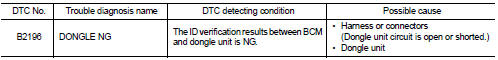
Nissan Juke Service and Repair Manual : B2196 dongle unit
Description
BCM performs ID verification between BCM and dongle unit.
When verification result is OK, BCM permits cranking.
DTC Logic
DTC DETECTION LOGIC
DTC CONFIRMATION PROCEDURE
1.PERFORM DTC CONFIRMATION PROCEDURE
1. Turn ignition switch ON.
2. Turn ignition switch OFF.
3. Turn ignition switch ON.
4. Check DTC in “Self-diagnosis result” mode of “BCM” using CONSULT-III.
Is the DTC detected? YES >> Refer to SEC-63, "Diagnosis Procedure".
NO >> INSPECTION END
Diagnosis Procedure
1.PERFORM INITIALIZATION
1. Perform initialization of BCM and reregistration of all Intelligent Keys using CONSULT-III.
For initialization and registration procedures, refer to CONSULT-III Operation Manual NATS-IVIS/NVIS.
2. Start the engine.
Dose the engine start? YES >> INSPECTION END
NO >> GO TO 2.
2.CHECK DONGLE UNIT CIRCUIT
1. Turn ignition switch OFF.
2. Disconnect BCM connector and dongle unit connector.
3. Check continuity between BCM harness connector and dongle unit harness connector.

4. Check continuity between BCM harness connector and ground.

Is the inspection result normal? YES >> GO TO 3.
NO >> Repair or replace harness.
3.CHECK DONGLE UNIT GROUND CIRCUIT
Check continuity between dongle unit harness connector and ground.

Is the inspection result normal? YES >> Replace dongle unit.
NO >> Repair or replace harness.
 B2195 anti-scanning
DTC Logic
DTC DETECTION LOGIC
DTC CONFIRMATION PROCEDURE
1.PERFORM DTC CONFIRMATION PROCEDURE
1. Turn ignition switch ON.
2. Check DTC in “Self Diagnostic Result” mode of “BCM” using CONSULT-II ...
 B2198 nats antenna AMP.
DTC Logic
DTC DETECTION LOGIC
DTC CONFIRMATION PROCEDURE
1.PERFORM DTC CONFIRMATION PROCEDURE 1
1. Contact Intelligent Key backside to push-button ignition switch.
2. Check DTC in “Self Diagnos ...
Other materials:
Basic inspection
DIAGNOSIS AND REPAIR WORK FLOW
Work Flow
OVERALL SEQUENCE
DETAILED FLOW
NOTE:
If any malfunction is found, immediately disconnect the battery cable from the
negative terminal.
1.CHECK ENGINE START
Crank the engine and check that the engine starts.
Does the engine start?
YES >> ...
Tire chains
Use of tire chains may be prohibited according to location. Check the local laws
before installing tire chains. When installing tire chains, make sure they are the
proper size for the tires on your vehicle and are installed according to the chain
manufacturer’s suggestions. Use only SAE Class ...
P2135 TP sensor
DTC Logic
DTC DETECTION LOGIC
NOTE:
If DTC P2135 is displayed with DTC P0643, first perform the trouble diagnosis
for DTC P0643. Refer to
EC-686, "DTC Logic".
DTC CONFIRMATION PROCEDURE
1.PRECONDITIONING
If DTC Confirmation Procedure has been previously conducted, always turn
...