Nissan Juke Service and Repair Manual : B210D starter relay
DTC Logic
DTC DETECTION LOGIC
NOTE
:
If DTC B210D is displayed with DTC U1000, first perform the trouble diagnosis
for DTC U1000. Refer to PCS-
30, "DTC Logic".

DTC CONFIRMATION PROCEDURE
1.PERFORM DTC CONFIRMATION PROCEDURE 1
1. Press push-button ignition switch under the following conditions to start engine, and wait 5 seconds or more.
- Selector lever: In the P position - Brake pedal: Depressed 2. Check DTC in “Self Diagnostic Result” mode of “IPDM E/R” using CONSULT-III.
Is DTC detected? YES >> Go to SEC-146, "Diagnosis Procedure".
NO >> GO TO 2.
2.PERFORM DTC CONFIRMATION PROCEDURE 2
1. Stop engine.
2. Perform DTC CONFIRMATION PROCEDURE for DTC P1650. Refer to EC-366, "DTC Logic" (MR16DDT) or EC-725, "DTC Logic" (HR16DE).
3. Turn ignition switch ON.
4. Check DTC in “Self Diagnostic Result” mode of “IPDM E/R” using CONSULT-III.
Is DTC detected? YES >> Refer to SEC-144, "Diagnosis Procedure".
NO >> INSPECTION END
Diagnosis Procedure
1.INSPECTION START
Perform inspection in accordance with procedure that confirms DTC.
Which procedure confirms DTC? DTC confirmation procedure 1>>GO TO 2.
DTC confirmation procedure 2>>GO TO 3.
2.INSPECTION START
1. Turn ignition switch ON.
2. Select “Self Diagnostic Result” mode of “IPDM E/R” using CONSULT-III.
3. Touch “ERASE”.
4. Perform DTC CONFIRMATION PROCEDURE for DTC B210D. Refer to SEC-146, "DTC Logic".
Is DTC detected? YES >> Replace IPDM E/R. Refer to PCS-34, "Removal and Installation".
NO >> INSPECTION END
3.CHECK IGNITION POWER SUPLLY NO.2 SIGNAL
1. Turn ignition switch OFF.
2. Disconnect IPDM E/R connector.
3. Check voltage between IPDM E/R harness connector and ground.

Is the inspection result normal? YES >> Replace IPDM E/R. Refer to PCS-34, "Removal and Installation".
NO >> GO TO 4.
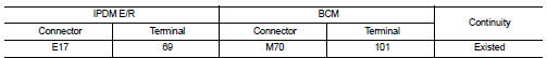
4.CHECK BCM INPUT SIGNAL CIRCUIT
1. Disconnect BCM connector.
2. Check continuity between IPDM E/R harness connector and BCM harness connector.
3. Check continuity between transmission range switch harness connector and ground.

Is the inspection result normal? YES >> GO TO 5.
NO >> Repair or replace harness.
5.REPLACE BCM
1. Replace BCM. Refer to BCS-93, "Removal and Installation".
2. Perform DTC CONFIRMATION PROCEDURE for DTC B210D Refer to SEC-146, "DTC Logic".
Is the inspection result normal? YES >> INSPECTION END
NO >> Replace IPDM E/R. Refer to PCS-34, "Removal and Installation".
 B210C starter control relay
DTC Logic
DTC DETECTION LOGIC
NOTE:
• If DTC B210C is displayed with DTC U1000, first perform the trouble diagnosis
for DTC U1000. Refer to
PCS-30, "DTC Logic".
• When IPDM E/R power ...
 B210E starter relay
DTC Logic
DTC DETECTION LOGIC
NOTE:
• If DTC B210E is displayed with DTC U1000, first perform the trouble diagnosis
for DTC U1000. Refer to
PCS-30, "DTC Logic".
• If DTC B210E is disp ...
Other materials:
Insufficient heating
Description
Symptom
• Insufficient heating
• No warm air comes out. (Air flow volume is normal.)
Diagnosis Procedure
NOTE:
Perform self-diagnosis with CONSULT-III before performing symptom diagnosis. If
any malfunction result or
DTC is detected, perform the corresponding diagnosis.
1.CHE ...
Engine unit
Disassembly
1. Remove intake manifold. Refer to EM-163, "Exploded View".
2. Remove exhaust manifold. Refer to EM-166, "Exploded View".
3. Remove oil pan (lower). Refer to EM-169, "Exploded View".
4. Remove ignition coil, spark plug, and rocker cover. Refer to EM-17 ...
B1170, B1171, B1172, B1173, B1174, B1175 diagnosis sensor uniT
DTC Logic
DTC DETECTION LOGIC
DTC CONFIRMATION PROCEDURE
1.CHECK SELF-DIAG RESULT
With CONSULT-III
1. Turn ignition switch ON.
2. Perform “Self Diagnostic Result” mode of “AIR BAG” using CONSULT-III.
Without CONSULT-III
1. Turn ignition switch ON.
2. Check the air bag warning lamp statu ...