Nissan Juke Service and Repair Manual : Turbocharger
Exploded View
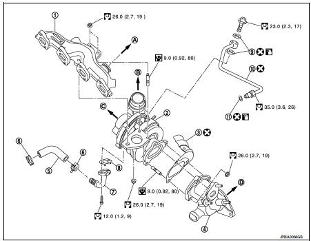
1. Exhaust manifold
2. Turbocharger
3. Gasket
4. Turbocharger outlet duct
5. Oil outlet hose
6. Clamp
7. Oil return pipe
8. Gasket
9. Washer
10. Oil supply tube
11. O-ring
A. To EGR tube
B. To air inlet pipe
C. To turbocharge air inlet pipe
D. To diesel particular filter assembly
 : N·m (kg-m, ft-lb)
 : N·m (kg-m, in-lb)
 : Always replace after every
disassembly.
 : Should be lubricated with oil.
Removal and Installation
REMOVAL
1. Remove air cleaner case. Refer to EM-280, "Exploded View".
2. Remove cowl top extension. Refer to EXT-20, "Exploded View".
3. Drain engine coolant. Refer to CO-62, "Draining".
4. Remove diesel particular filter assembly. Refer to EX-17, "Exploded View".
5. Remove EGR volume control valve housing. Refer to EM-283, "Exploded View".
6. Remove EGR cooler.
7. Disconnect 5th injector quick connector and harness connector.
8. Remove oil tubes.
9. Remove turbocharger outlet duct bracket.
10. Remove turbocharger assembly (1) as follows:
NOTE
:
After applying penetrative lubricant to the mounting nuts, check for the
penetration of the lubricant, and
then loosen the nuts (A) to remove.
a. Remove turbocharger oil outlet hose.
CAUTION:
Be careful not to deform each turbocharger piping when pulling
out the assembly.

11. Remove turbocharger outlet duct.
INSTALLATION
Install in the reverse order of removal.
NOTE
:
Apply LOCTITE FRENETANCH or equivalent to the threads of the turbocharger oil
inlet pipe union to the cylinder
head.
Inspection
INSPECTION AFTER REMOVAL
Turbocharger

CAUTION:
When the compressor wheel, turbine wheel or rotor shaft is damaged, remove all
the fragments and
foreign matter left in the following passages in order to prevent a secondary
failure:
Suction side : Between turbocharger and air cleaner Exhaust side : Between turbocharger and outlet duct
INSPECTION AFTER INSTALLATION
Start engine and raise engine speed to check no exhaust emission leaks.
 EGR valve
Exploded View
1. EGR valve assembly
2. Clamp
3. EGR tube
4. Air inlet tube
5. O-ring
6. Gasket
7. EGR cooler
8. Gasket
9. EGR volume control valve housing
10. Gasket
11. Electric t ...
 Exhaust manifold
Exploded View
1. Exhaust gas temperature sensor 1
2. Gasket
3. Exhaust manifold
4. Exhaust gas pressure sensor 1
A. To cylinder head
: N·m (kg-m, ft-lb)
: Always replace after every
disas ...
Other materials:
How to use remote keyless entry function
WARNING
• Radio waves could adversely affect electric medical equipment. Those who
use a pacemaker should contact the electric medical equipment manufacturer for the
possible influences before use.
• The Intelligent Key transmits radio waves when the buttons are pushed. The
FAA advises ...
U1000 can comm circuit
Description
CAN (Controller Area Network) is a serial communication system for real time
application. It is an on-vehicle
multiplex communication system with high data communication speed and excellent
error detectability. Many
electronic control units are equipped onto vehicles, and each con ...
Body alignment
Body Center Marks (RHD Models)
A mark is placed on each part of the body to indicate the vehicle center.
When repairing the vehicle frame
(members, pillars, etc.) damaged by an accident which it enables more accurate
and effective repair by using
these marks together with body alignment speci ...
