Nissan Juke Service and Repair Manual : System
System Description
Fan speed of blower motor is changed by the combination of fan control dial (fan switch) operation and blower fan resistor control.
Door Control
SWITCHES AND THEIR CONTROL FUNCTIONS
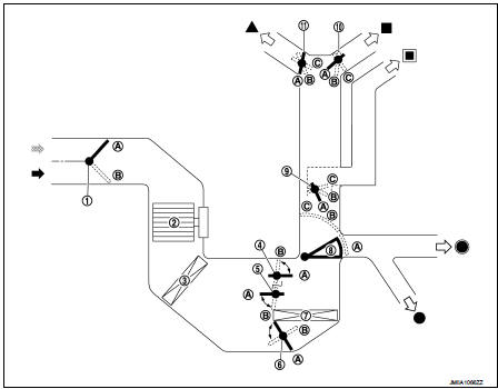
1. Intake door
2. Blower motor
3. Air conditioner filter
4. Max. cool door
5. Upper air mix door
6. Lower air mix door
7. Heater core
8. Foot door
9. Side ventilator door
10. Center ventilator door
11. Defroster door
 Fresh air intake
 Recirculation air
 Defroster
 Center ventilator
 Side ventilator
 Foot
Foot
 Rear foot*
*: With rear foot duct
AIR DISTRIBUTION
Without rear foot duct

With rear foot duct

 Component parts
Component Part Location
1. BCM
Refer to BCS-161, "Removal and Installation".
2. Heater control
3. Blower fan resistor
4. Blower motor
A. Left side of heater unit assembly
B. Right ...
 Operation
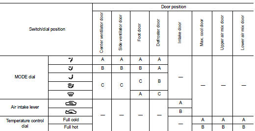
Switch Name and Function
HEATER CONTROLLER (HEATER CONTROL)
1. MODE dial
2. Fan control dial
3. Temperature control dial
4. Intake lever
...
Other materials:
Combination switch output circuit
Diagnosis Procedure
1.CHECK OUTPUT 1 - 5 CIRCUIT FOR OPEN
1. Turn ignition switch OFF.
2. Disconnect BCM and combination switch connectors.
3. Check continuity between BCM harness connector and combination switch harness
connector
Does continuity exist?
YES >> GO TO 2.
NO >> ...
Precaution Necessary for Steering Wheel Rotation after Battery Disconnect
NOTE:
• Before removing and installing any control units, first turn the ignition
switch to the LOCK position, then disconnect
both battery cables.
• After finishing work, confirm that all control unit connectors are connected
properly, then re-connect both
battery cables.
• Always use CONS ...
BCM branch line circuit
Diagnosis Procedure
1.CHECK CONNECTOR
1. Turn the ignition switch OFF.
2. Disconnect the battery cable from the negative terminal.
3. Check the terminals and connectors of the BCM for damage, bend and loose
connection (unit side and
connector side).
Is the inspection result normal?
YES &g ...
