Nissan Juke Service and Repair Manual : System
Starting system (with intelligent key) : System Diagram

*1: M/T models
*2: CVT models
Starting system (with intelligent key) : System Description
CVT MODELS
• When selector lever is P or N, power is supplied to starter relay and starter control relay by transmission range switch. And BCM and IPDM E/R (CPU) detect selector lever P/N condition by the inputted signal.
• When starter operating condition is satisfied, IPDM E/R turns starter control relay ON by starter control relay control signal.
• When engine cranking condition is satisfied, BCM turns starter relay ON by starter control relay control signal.
• Then battery power is supplied to starter motor (“S” terminal) through starter control relay and starter relay.
M/T MODELS
• When the ignition switch is turned ON or START position power is supplied to starter relay and starter control relay. And BCM and IPDM E/R (CPU) detect ignition switch position by the inputted signal.
• When starter operating condition is satisfied, IPDM E/R turns starter control relay ON by starter control relay control signal.
• When engine cranking condition is satisfied, BCM turns starter relay ON by starter control relay control signal.
• Then battery power is supplied to starter motor (“S” terminal) through starter control relay and starter relay.
Starting system (without intelligent key) : System Diagram
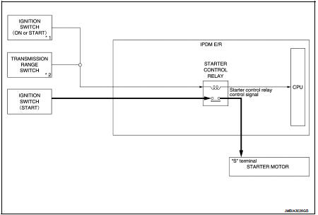
*1: M/T models
*2: CVT model
Starting system (without intelligent key) : System Description
CVT MODELS
• When selector lever is P or N, power is supplied to starter control relay by transmission range switch. And IPDM E/R (CPU) detect selector lever P/N condition by the inputted signal.
• When engine cranking condition is satisfied, then battery power is supplied to starter motor (“S” terminal) through starter control relay.
M/T MODELS
When ignition switch is START position, battery power is supplied to starter motor (“S” terminal).
 Component parts
Starting system (with intelligent key) : Component Parts Location
1. IPDM E/R
Refer to PCS-5, "Component Parts
Location".
2. Transmission range switch (CVT
models)
Refer to TM-131, & ...
 Wiring diagram
...
Other materials:
Push-button ignition switch position indicator does not illuminate
Description
• Before performing the diagnosis in the following table, check “Work Flow”.
Refer to PCS-88, "Work Flow".
• Check that vehicle is under the condition shown in “Conditions of vehicle”
before starting diagnosis, and
check each symptom.
Conditions of Vehicle (Operating ...
Precaution Necessary for Steering Wheel Rotation after Battery Disconnect
NOTE:
• Before removing and installing any control units, first turn the ignition
switch to the LOCK position, then disconnect
both battery cables.
• After finishing work, confirm that all control unit connectors are connected
properly, then re-connect both
battery cables.
• Always use CONS ...
B1218, B1219, B1220, B1221, B1222, B1223 diagnosis sensor unit
DTC Logic
DTC DETECTION LOGIC
DTC CONFIRMATION PROCEDURE
1.CHECK SELF-DIAG RESULT
With CONSULT-III
1. Turn ignition switch ON.
2. Perform “Self Diagnostic Result” mode of “AIR BAG” using CONSULT-III.
Without CONSULT-III
1. Turn ignition switch ON.
2. Check the air bag warning lamp statu ...
