Nissan Juke Service and Repair Manual : Side oil seal
Exploded View
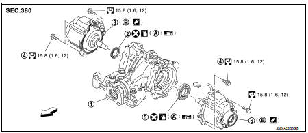
1. Rear final drive assembly
2. Side oil seal (right)
3. Electric controlled coupling (right)
4. Reamer bolt
5. Side oil seal (left)
6. Electric controlled coupling (left)
A. Oil seal lip B. Gear carrier mouting face
 : Vehicle front
 : N·m (kg-m, ft-lb)
 : Always replace after every
disassembly.
 : Apply multi purpose grease
 : Apply gear oil.
 : Apply Genuine Liquid Gasket 1217
or equivalent.
Removal and Installation
REMOVAL
1. Remove electric controlled couplings. Refer to DLN-139, "Removal and Installation".
2. Remove side oil seals with a suitable tool.
CAUTION:
Never damage gear carrier and rear cover.

INSTALLATION
1. Install side oil seal (right side) until it becomes flush with the carrier end, using the drift (A) (SST: KV38100200).
CAUTION:
• Never reuse oil seals.
• When installing, never incline oil seals.
• Apply multi-purpose grease onto oil seal lips, and gear oil onto the circumference of oil seal
.

2. Install side oil seal (left side) until it becomes flush with the carrier end, using the drift (A) (SST: KV38100500).
CAUTION:
• Never reuse oil seals.
• When installing, never incline oil seals.
• Apply multi-purpose grease onto oil seal lips, and gear oil onto the circumference of oil seal.
3. Install electric controlled couplings. Refer to DLN-139, "Removal and Installation".
4. When oil leaks while removing, check oil level after the installation.
Refer to DLN-132, "Inspection".

 Front oil seal
Exploded View
1. Rear final drive assembly
2. Front oil seal
3. Companion flange
4. Companion flange lock nut
A. Oil seal lip
: Vehicle front
: N·m (kg-m, ft-lb)
: Never reuse parts
: App ...
 Electric controlled coupling
Exploded View
1. Sub-harness
2. Rear final drive assembly
3. Electric controlled coupling (right)
4. Reamer bolt
5. Electric controlled coupling (left)
A. Gear carrier mouting face
: Vehic ...
Other materials:
Front drive shaft
Exploded View
LEFT SIDE
1. Circular clip
2. Dust shield
3. Housing assembly
4. Boot band
5. Boot
6. Damper band
7. Dynamic damper
8. Circular clip
9. Joint sub-assembly
: Wheel side
: Fill NISSAN Genuine grease or
equivalent.
: Always replace after every
disassembly.
RIGHT ...
Clutch pedal
Inspection and Adjustment
INSPECTION
The Height of Clutch Pedal
1. Turn the floor carpet.
2. Check that the clutch pedal height “H1” from the dash lower
panel (1) is within the reference value.
Clutch pedal height
“H1”
: Refer to CL-35, "Clutch Pedal".
3. Replace clutch pedal if t ...
All defogger system dose not operate
Description
Rear window defogger and door mirror defogger do not operate when rear window
defogger switch operated.
Diagnosis Procedure
1.CHECK REAR WINDOW DEFOGGER SWITCH
Check rear window defogger switch.
Refer to DEF-26, "WITH AUTO A/C : Component Function Check" (With Auto A/C ...
