Nissan Juke Service and Repair Manual : Remote keyless entry receiver
Component Function Check
1.CHECK FUNCTION
1. Select “INTELLIGENT KEY” of “BCM” using CONSULT-III.
2. Select “RKE OPE COUN1” in “DATA MONITOR” mode.
3. Check that the function operates normally according to the following conditions.

Is the inspection result normal? YES >> Remote keyless entry receiver is OK.
NO >> Refer to DLK-95, "Diagnosis Procedure".
Diagnosis Procedure
1.CHECK REMOTE KEYLESS ENTRY RECEIVER GROUND CIRCUIT
1. Turn ignition switch OFF.
2. Disconnect BCM connector and remote keyless entry receiver connector.
3. Check continuity between BCM harness connector and remote keyless entry receiver harness connector.

4. Check continuity between BCM harness connector and ground.
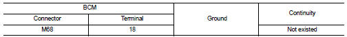
Is the inspection result normal? YES >> GO TO 2.
NO >> Repair or replace harness.
2.CHECK REMOTE KEYLESS ENTRY RECEIVER POWER SUPPLY
1. Reconnect BCM connector.
2. Check voltage between remote keyless entry receiver harness connector and ground.

Is the inspection result normal? YES >> GO TO 4.
NO >> GO TO 3.
3.CHECK REMOTE KEYLESS ENTRY RECEIVER CIRCUIT 1
1. Disconnect BCM connector 2. Check continuity between BCM harness connector and remote keyless entry receiver harness connector.

3. Check continuity between BCM harness connector and ground.

Is the inspection result normal? YES >> Replace BCM. Refer to BCS-93, "Removal and Installation".
NO >> Repair or replace harness.
4.CHECK REMOTE KEYLESS ENTRY RECEIVER OUTPUT SIGNAL
1. Reconnect remote keyless entry receiver connector.
2. Check signal between remote keyless entry receiver harness connector and ground using oscilloscope.

Is the inspection result normal? YES >> GO TO 5.
NO >> Replace remote keyless entry receiver.
5.CHECK REMOTE KEYLESS ENTRY RECEIVER CIRCUIT 2
1. Disconnect BCM connector and remote keyless entry receiver connector.
2. Check continuity between BCM harness connector and remote keyless entry receiver harness connector.

3. Check continuity between BCM harness connector and ground.

Is the inspection result normal? YES >> GO TO 6.
NO >> Repair or replace harness.
6.CHECK REMOTE KEYLESS ENTRY RECEIVER RSSI OUTPUT SIGNAL
1. Reconnect BCM and remote keyless entry receiver connector.
2. Check signal between remote keyless entry receiver harness connector and ground using oscilloscope.

Is the inspection result normal? YES >> GO TO 7.
NO >> Replace remote keyless entry receiver.
7.CHECK REMOTE KEYLESS ENTRY RECEIVER RSSI CIRCUIT
1. Disconnect BCM and remote keyless entry receiver connector.
2. Check continuity between BCM harness connector and remote keyless entry receiver harness connector.

3. Check continuity between BCM harness connector and ground.

Is the inspection result normal? YES >> Replace BCM. Refer to BCS-93, "Removal and Installation".
NO >> Repair or replace harness.
 Key warning lamp
Component Function Check
1.CHECK FUNCTION
1. Select “INTELLIGENT KEY” of “BCM” using CONSULT-III.
2. Select “INDICATOR” in “ACTIVE TEST” mode.
3. Check that the function operates normally accordin ...
 Shift P warning lamp
Component Function Check
1.CHECK FUNCTION
1. Select “INTELLIGENT KEY” of “BCM” using CONSULT-III.
2. Select “LCD” in “ACTIVE TEST” mode.
3. Check that the function operates normally according to t ...
Other materials:
B2602 shift position
DTC Logic
DTC DETECTION LOGIC
NOTE:
• If DTC B2602 is displayed with DTC U1000, first perform the trouble diagnosis
for DTC U1000. Refer to
BCS-83, "DTC Logic".
• If DTC B2602 is displayed with DTC U1010, first perform the trouble diagnosis
for DTC U1010. Refer to
BCS-84, "D ...
License plate lamp
Exploded View
1. License plate lamp housing assembly
2. Blub
3. License plate lamp blub socket
: Pawl
Removal and Installation
CAUTION:
Disconnect battery negative terminal or remove the fuse.
REMOVAL
1. While pressing the license plate lamp to direction right side, pull
it to directio ...
Diagnosis system (combination meter)
On Board Diagnosis Function
ON BOARD DIAGNOSIS ITEM
The combination meter allows the following diagnosis items with the on-board
diagnosis function.
METHOD OF STARTING
1. Turn ignition switch ON, and switch the trip meter to “trip A” or “trip
B”.
2. Turn ignition switch OFF.
3. While pre ...
