Nissan Juke Service and Repair Manual : Power supply and ground circuit
Diagnosis Procedure
1.CHECK GROUND CONNECTION
1. Turn ignition switch OFF.
2. Check ground connection E21 and E38. Refer to Ground Inspection in GI-44, "Circuit Inspection".
Is the inspection result normal? YES >> GO TO 2.
NO >> Repair or replace ground connection.
2.CHECK ECM GROUND CIRCUIT FOR OPEN AND SHORT
1. Disconnect ECM harness connectors.
2. Check the continuity between ECM harness connector and ground.

3. Also check harness for short to power.
Is the inspection result normal? YES >> GO TO 4.
NO >> GO TO 3.
3.DETECT MALFUNCTIONING PART
Check the following.
• Harness connectors E8, F1 • Harness for open or short between ECM and ground
>> Repair open circuit or short to power in harness or connectors.
4.CHECK ECM POWER SUPPLY CIRCUIT-I
1. Reconnect ECM harness connectors.
2. Turn ignition switch ON.
3. Check the voltage between ECM harness connector and ground.

Is the inspection result normal? YES >> GO TO 6.
NO >> GO TO 5.
5.DETECT MALFUNCTIONING PART
Check the following.
• 15 A fuse (No. 62)
• Harness for open or short between ECM and fuse
>> Repair open circuit or short to ground or short to power in harness or connectors.
6.CHECK ECM POWER SUPPLY CIRCUIT-II
1. Turn ignition switch OFF and wait at least 10 seconds.
2. Turn ignition switch ON and then OFF.
Check the voltage between ECM harness connector and ground.

Is the inspection result normal? YES >> GO TO 7.
NO >> GO TO 9.
7.CHECK ECM POWER SUPPLY CIRCUIT-III
1. Turn ignition switch ON.
2. Check the voltage between IPDM E/R harness connector and ground.

Is the inspection result normal? YES >> GO TO 8.
NO >> Replace IPDM E/R.
8.CHECK INTERMITTENT INCIDENT
Refer to GI-42, "Intermittent Incident".
>> INSPECTION END
9.CHECK ECM POWER SUPPLY CIRCUIT-IV
1. Turn ignition switch OFF and wait at least 10 seconds.
2. Check the voltage between ECM harness connector and ground.

Is the inspection result normal? YES >> GO TO 13.
NO >> GO TO 10.
10.CHECK ECM POWER SUPPLY CIRCUIT-V
1. Disconnect ECM harness connector.
2. Disconnect IPDM E/R harness connector E14.
3. Check the continuity between ECM harness connector and IPDM E/R harness connector.

4. Also check harness for short to ground and short to power.
Is the inspection result normal? YES >> GO TO 12.
NO >> GO TO 11.
11.DETECT MALFUNCTIONING PART
Check the following.
• Harness connectors E8, F1 • Harness for open or short between ECM and IPDM E/R
>> Repair open circuit or short to ground or short to power in harness or connectors.
12.CHECK 20 A FUSE
1. Disconnect 20 A fuse (No. 43) from IPDM E/R.
2. Check 20 A fuse.
Is the inspection result normal? YES >> GO TO 14.
NO >> Replace 20 A fuse.
13.CHECK ECM POWER SUPPLY CIRCUIT-VI
1. Disconnect ECM harness connector.
2. Disconnect IPDM E/R harness connector E14.
3. Check the continuity between ECM harness connector and IPDM E/R harness connector.
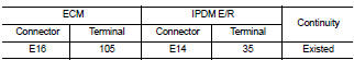
4. Also check harness for short to ground and short to power.
Is the inspection result normal? YES >> GO TO 14.
NO >> Repair open circuit or short to ground or short power in harness or connectors.
14.CHECK INTERMITTENT INCIDENT
Refer to GI-42, "Intermittent Incident".
Is the inspection result normal? YES >> Replace IPDM E/R.
NO >> Repair or replace harness or connectors.
 Trouble diagnosis - specification valuE
Description
The specification (SP) value indicates the tolerance of the value that is
displayed in “SPEC” of “DATA MONITOR”
mode of CONSULT-III during normal operation of the Engine Control System ...
 U1000, U1001 CAN COMM CIRCUIT
Description
CAN (Controller Area Network) is a serial communication line for real time
application. It is an on-vehicle multiplex
communication line with high data communication speed and excellen ...
Other materials:
Inspection
OIL LEAKAGE
Check transfer surrounding area (oil seal, drain plug, filler plug, and
transfer case etc.) for oil leakage.
OIL LEVEL
1. Remove filler plug (1) and gasket. Then check that oil is filled up
from mounting hole for the filler plug.
Vehicle front
CAUTION:
Never start engine while ...
Back door lock
Exploded View
1. Back door lock assembly
2. TORX bolt
3. Back door striker
: Do not reuse
: N·m (kg-m, ft-lb)
: Body grease
Door lock
DOOR LOCK : Removal and Installation
REMOVAL
1. Remove the back door lower finisher. Refer to INT-35, "BACK DOOR LOWER
FINISHER : Removal and
In ...
Thermostat
Inspection
• Place a thread so that it is caught in the valves of the thermostat.
Immerse fully in a container filled with water. Heat while stirring.
(The example in the figure shows the thermostat.)
• The valve opening temperature is the temperature at which the
valve opens and falls from ...
