Nissan Juke Service and Repair Manual : Power supply and ground circuit
Diagnosis Procedure
1.CHECK 4WD CONTROL MODULE POWER SUPPLY (1)
1. Turn the ignition switch OFF.
2. Disconnect 4WD control module harness connector.
3. Check the voltage between 4WD control module harness connector and ground.

4. Turn the ignition switch ON.
CAUTION:
Never start the engine.
5. Check the voltage between 4WD control module harness connector and ground.

Is the inspection result normal? YES >> GO TO 3.
NO >> GO TO 2.
2.CHECK 4WD CONTROL MODULE POWER SUPPLY (2)
1. Turn the ignition switch OFF.
2. Check the 10A fuse (#33).
3. Check the harness for open or short between 4WD control module harness connector No.1 terminal and 10A (#33).
Is the inspection result normal? YES >> Perform the trouble diagnosis for power supply circuit. Refer to PG-10, "Wiring Diagram - BATTERY POWER SUPPLY -".
NO >> Repair or replace error-detected parts.
3.CHECK 4WD CONTROL MODULE POWER SUPPLY (3)
1. Turn the ignition switch OFF.
2. Check the voltage between 4WD control module harness connector and ground.
3. Turn the ignition switch ON.
CAUTION:
Never start the engine.
4. Check the voltage between 4WD control module harness connector and ground.

Is the inspection result normal? YES >> GO TO 5.
NO >> GO TO 4.
4.CHECK 4WD CONTROL MODULE POWER SUPPLY (4)
1. Turn the ignition switch OFF.
2. Check the 10A fuse (#3).
3. Check the harness for open or short between 4WD control module harness connector No.3 terminal and 10A (#3).
Is the inspection result normal? YES >> Perform the trouble diagnosis for ignition power supply circuit. Refer to PG-15, "Wiring Diagram - IGNITION POWER SUPPLY -".
NO >> Repair or replace error-detected parts.
5.CHECK 4WD SOLENOID POWER SUPPLY (1)
1. Turn the ignition switch OFF.
2. Disconnect 4WD control module harness connector.
3. Check the voltage between 4WD control module harness connector and ground.

4. Turn the ignition switch OFF to ON.
CAUTION:
Never start the engine.
5. Check the voltage between 4WD control module harness connector and ground.

Is the inspection result normal? YES >> GO TO 7.
NO >> GO TO 6.
6.CHECK 4WD SOLENOID POWER SUPPLY (2)
1. Turn the ignition switch OFF.
2. Check the 10A fuse (#12).
3. Check the harness for open or short between 4WD control module harness connector No.12 and the 10A fuse (#12).
Is the inspection result normal? YES >> Perform the trouble the diagnosis for power supply circuit. Refer to PG-10, "Wiring Diagram - BATTERY POWER SUPPLY -".
NO >> Repair or replace error-detected parts.
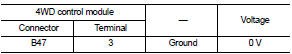
7.CHECK 4WD CONTROL MODULE GROUND
1. Turn the ignition switch OFF.
2. Check the continuity between 4WD control module harness connector and ground.

Is the inspection result normal? YES >> INSPECTION END
NO >> Repair or replace error-detected parts.
 U1010 control unit (CAN)
Description
CAN (Controller Area Network) is a serial communication line for real time
application. It is an on-vehicle multiplex
communication line with high data communication speed and excellen ...
 4WD warning lamp
Component Function Check
1.CHECK 4WD WARNING LAMP FUNCTION
1. Turn the ignition switch ON.
2. Check that 4WD warning lamp turns on.
Is the inspection result normal?
YES >> INSPECTION END
...
Other materials:
Insufficient heating
Description
Symptom
• Insufficient heating
• No warm air comes out. (Air flow volume is normal.)
Diagnosis Procedure
NOTE:
Perform self-diagnoses with CONSULT-III before performing symptom diagnosis. If
any DTC is detected, perform
the corresponding diagnosis.
1.CHECK COOLING SYSTEM
1. ...
Parking/parking on hills
WARNING
• Do not stop or park the vehicle over flammable materials such as dry grass,
waste paper or rags. They may ignite and cause a fire.
• Never leave the engine running while the vehicle is unattended.
• Do not leave children unattended inside the vehicle. They could unknowingly activate ...
Diagnosis and repair work flow
Work Flow
DETAILED FLOW
1.INTERVIEW FROM THE CUSTOMER
Clarify customer complaints before inspection. First of all, perform an
interview utilizing BRC-146, "Diagnostic
Work Sheet" and reproduce the symptom as well as fully understand it. Ask
customer about his/her complaints
carefu ...
