Nissan Juke Service and Repair Manual : P1811 power supply circuit for 4wd control module
DTC Logic
DTC DETECTION LOGIC
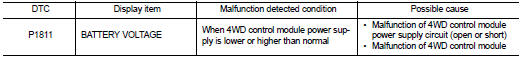
DTC CONFIRMATION PROCEDURE
1.PRECONDITIONING
If “DTC CONFIRMATION PROCEDURE” has been previously conducted, always turn ignition switch OFF and wait at least 10 seconds before conducting the next test.
>> GO TO 2.
2.DTC REPRODUCTION PROCEDURE
 With CONSULT-III
1. Turn the ignition switch OFF to ON.
2. Perform self-diagnosis for “ALL MODE AWD/4WD”.
Is DTC “P1811” detected? YES >> Proceed to diagnosis procedure. Refer to DLN-42, "Diagnosis Procedure".
NO >> INSPECTION END
Diagnosis Procedure
1.CHECK 4WD CONTROL MODULE POWER SUPPLY (1)
1. Turn the ignition switch OFF.
2. Disconnect 4WD control module harness connector.
3. Check the voltage between 4WD control module harness connector and ground.

4. Turn the ignition switch ON.
CAUTION:
Never start the engine.
5. Check the voltage between 4WD control module harness connector and ground.

Is the inspection result normal? YES >> GO TO 3.
NO >> GO TO 2.
2.CHECK 4WD CONTROL MODULE POWER SUPPLY (2
)
1. Turn the ignition switch OFF.
2. Check the 10A fuse (#33).
3. Check the harness for open or short between 4WD control module harness connector No.1 terminal and 10A (#33).
Is the inspection result normal?
YES >> Perform the trouble diagnosis for power supply circuit. Refer to PG-10, "Wiring Diagram - BATTERY POWER SUPPLY -".
NO >> Repair or replace error-detected parts.
3.CHECK 4WD CONTROL MODULE POWER SUPPLY (3)
1. Turn the ignition switch OFF.
2. Check the voltage between 4WD control module harness connector and ground.
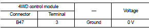
3. Turn the ignition switch ON.
CAUTION:
Never start the engine.
4. Check the voltage between 4WD control module harness connector and ground.

Is the inspection result normal? YES >> GO TO 5.
NO >> GO TO 4.
4.CHECK 4WD CONTROL MODULE POWER SUPPLY (4)
1. Turn the ignition switch OFF.
2. Check the 10A fuse (#3).
3. Check the harness for open or short between 4WD control module harness connector No.3 terminal and 10A (#3).
Is the inspection result normal? YES >> Perform the trouble diagnosis for ignition power supply circuit. Refer to PG-15, "Wiring Diagram - IGNITION POWER SUPPLY -".
NO >> Repair or replace error-detected parts.
5.CHECK 4WD CONTROL MODULE GROUND
1. Turn the ignition switch OFF.
2. Check the continuity between 4WD control module harness connector and ground.

Is the inspection result normal? YES >> GO TO 6.
NO >> Repair or replace error-detected parts.
6.CHECK TERMINALS AND HARNESS CONNECTORS
Check the 4WD control module pin terminals for damage or loose connection with harness connector.
Is the inspection result normal? YES >> Replace 4WD control module. Refer to DLN-91, "Removal and Installation".
NO >> Repair or replace error-detected parts.
 P1808 Wheel speed sensor
DTC Logic
DTC DETECTION LOGIC
DTC CONFIRMATION PROCEDURE
1.PRECONDITIONING
If “DTC CONFIRMATION PROCEDURE” has been previously conducted, always turn
ignition switch OFF and
wait at least 10 ...
 P1813 4WD mode switch
DTC Logic
DTC DETECTION LOGIC
DTC CONFIRMATION PROCEDURE
1.PRECONDITIONING
If “DTC CONFIRMATION PROCEDURE” has been previously conducted, always turn
ignition switch OFF and
wait at least 10 ...
Other materials:
B1183 lap Pre-tensioner LH
DTC Logic
DTC CONFIRMATION PROCEDURE
1.CHECK SELF-DIAGNOSTIC RESULT
With CONSULT-III
1. Turn ignition switch ON.
2. Perform “Self Diagnostic Result” mode of “AIR BAG” using CONSULT-III.
Without CONSULT-III
1. Turn ignition switch ON.
2. Check the air bag warning lamp status. Refer to SRC ...
None of the power windows can be operated using any
switch
Diagnosis Procedure
1.CHECK BCM POWER SUPPLY AND GROUND CIRCUIT
Check BCM power supply and ground circuit. Refer to the following.
• With Intelligent Key: Refer to BCS-87, "Diagnosis Procedure".
• Without Intelligent Key: Refer to BCS-155, "Diagnosis Procedure".
Is the i ...
Engine overheating
Description
CHART 17: ENGINE OVERHEATING
Diagnosis Procedure
1.CHECK COOLING SYSTEM
Check the cooling system. Refer to CO-60, "Troubleshooting Chart".
Is the inspection result normal?
YES >> GO TO 2.
NO >> Repair or replace.
2.CHECK ECM POWER SUPPLY AND GROUND CIR ...
