Nissan Juke Service and Repair Manual : P1642 thermoplunger control unit
DTC Logic
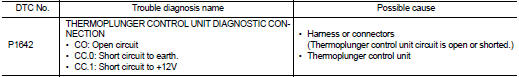
DTC DETECTION LOGIC
Diagnosis Procedure
1.CHECK THERMOPLUNGER CONTROL UNIT POWER SUPPLY CIRCUIT
1. Turn ignition switch OFF.
2. Disconnect thermoplunger control unit harness connector.
3. Check the voltage between thermoplunger control unit harness connector and ground.

Is the inspection result normal? YES >> GO TO 3.
NO >> GO TO 2.
2.DETECT MALFUNCTIONING PART
Check the following.
• 100A fusible link (letter B) • Harness for open and short between thermoplunger control unit and battery
>> Repair open circuit or short to ground or short to power in harness or connectors.
3.CHECK THERMOPLUNGER CONTROL UNIT GROUND CIRCUIT FOR OPEN AND SHORT
1. Disconnect ECM harness connector.
2. Check the continuity between thermoplunger control unit harness connector and ECM harness connector.

3. Also check harness for short to ground and short to power.
Is the inspection result normal? YES >> GO TO 4.
NO >> Repair open circuit or short to ground or short to power in harness or connectors.
4.CHECK INTERMITTENT INCIDENT
Is the inspection result normal? YES >> Replace thermoplunger control unit.
NO >> Repair or replace.
 P1641 thermoplunger control unit
DTC Logic
DTC DETECTION LOGIC
Diagnosis Procedure
1.CHECK THERMOPLUNGER CONTROL UNIT POWER SUPPLY CIRCUIT
1. Turn ignition switch OFF.
2. Disconnect thermoplunger control unit harness connector ...
 P1643 thermoplunger control unit
DTC Logic
DTC DETECTION LOGIC
Diagnosis Procedure
1.CHECK THERMOPLUNGER CONTROL UNIT POWER SUPPLY CIRCUIT
1. Turn ignition switch OFF.
2. Disconnect thermoplunger control unit harness connector ...
Other materials:
Structure and operation
Sectional View
1. 5th input gear
2. 5th-reverse synchronizer hub assembly
3. Input shaft
4. Mainshaft
5. 5th main gear
6. Mainshaft rear bearing
7. 4th main gear
8. 3rd-4th synchronizer hub assembly
9. 3rd main gear
10. 2nd main gear
11. 1st-2nd synchronizer hub assembly
12. Dif ...
A/C switch
Component Function Check
1.CHECK A/C ON SIGNAL
With CONSULT-III
1. Turn ignition switch ON.
2. Select “AIR CONDITIONER” of “BCM” using CONSULT-III.
3. Select “AIR COND SW” in “DATA MONITOR” mode, and check status under the
following condition.
Is the inspection result normal?
YES >> ...
System
WITH AUTO A/C
WITH AUTO A/C : System Diagram
WITH AUTO A/C : System Description
OPERATION DESCRIPTION
• BCM detects that the rear window defogger switch turns ON when the ignition
switch is ON, and then transmits
the rear window defogger switch signal to IPDM E/R via CAN communication for
...
