Nissan Juke Service and Repair Manual : P0745 pressure control solenoid A
DTC Logic
DTC DETECTION LOGIC

DTC CONFIRMATION PROCEDURE
NOTE
:
If “DTC CONFIRMATION PROCEDURE” has been previously performed, always turn
ignition switch
OFF and wait at least 10 seconds before performing the next test.
After the repair, perform the following procedure to confirm the malfunction is eliminated.
1.CHECK DTC DETECTION
 With CONSULT-III
1. Turn ignition switch ON.
2. Start engine and wait at least 5 seconds.
3. Select “Self Diagnostic Results” in “TRANSMISSION”.
 With GST
Follow the procedure “With CONSULT-III”.
Is “P0745” detected? YES >> Go to TM-219, "Diagnosis Procedure".
NO >> Check intermittent incident. Refer to GI-42, "Intermittent Incident".
Diagnosis Procedure
1.CHECK LINE PRESSURE SOLENOID VALVE CIRCUIT
1. Turn ignition switch OFF.
2. Disconnect TCM connector.
3. Check resistance between TCM connector terminal and ground.

Is the inspection result normal? YES >> GO TO 4.
NO >> GO TO 2.
2.CHECK LINE PRESSURE SOLENOID VALVE
Check line pressure solenoid valve. Refer to TM-220, "Component Inspection" Is the inspection result normal? YES >> GO TO 3.
NO >> Repair or replace damaged parts.
3. CHECK HARNESS BETWEEN TCM AND LINE PRESSURE SOLENOID VALVE
1. Turn ignition switch OFF.
2. Disconnect CVT unit harness connector and TCM connector.
3. Check continuity between TCM connector terminal and CVT unit harness connector terminal.

4. If OK, check harness for short to ground and short to power.
5. If OK, check continuity between ground and CVT assembly.
6. Reinstall any part removed.
Is the inspection result normal? YES >> GO TO 4.
NO >> Repair or replace damaged parts.
4.CHECK TCM
Check TCM input/output signals. Refer to TM-164, "Reference Value".
Is the inspection result normal? YES >> Check intermittent incident. Refer to GI-42, "Intermittent Incident".
NO >> Replace the TCM. Refer to TM-280, "Removal and Installation".
Component Inspection
LINE PRESSURE SOLENOID VALVE
1.LINE PRESSURE SOLENOID VALVE
1. Turn ignition switch OFF.
2. Disconnect CVT unit harness connector.
3. Check resistance between CVT unit harness connector terminal and ground.
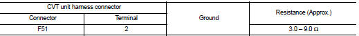
Is the inspection result normal? YES >> INSPECTION END
NO >> Replace the transaxle assembly. Refer to TM-301, "Removal and Installation"
 P0744 torque converter
Description
This malfunction is detected when the torque converter clutch does not
lock-up as instructed by the TCM. This
is not only caused by electrical malfunction (circuits open or shorted), b ...
 P0746 pressure control solenoid A
Description
The line pressure solenoid valve regulates the oil pump discharge pressure to
suit the driving condition in
response to a signal sent from the TCM.
DTC Logic
DTC DETECTION LOGIC
D ...
Other materials:
Brake booster
Exploded View
2WD
1. Master cylinder assembly
2. Vacuum pipe
3. Brake booster
4. Lock nut
5. Clevis
6. Gasket
7. Spacer
: N·m (kg-m, ft-lb)
4WD
1. Master cylinder assembly
2. Brake booster
3. Lock nut
4. Clevis
5. Gasket
6. Spacer
: N·m (kg-m, ft-lb)
Removal and install ...
Replacing
Replace the wiper blades if they are worn.
Before replacing the wiper blades, the wiper should be in the fully up position
to avoid scratching the engine hood or damaging the wiper arm. To pull up the wiper
arm, see “Windshield wiper and washer switch” .
1. Lift the wiper arm away from the w ...
Component parts
Component Part Location
1. BCM
• With Intelligent Key: Refer to BCS-
6, "BODY CONTROL SYSTEM :
Component Parts Location".
• Without Intelligent Key: Refer to
BCS-96, "BODY CONTROL SYSTEM
: Component Parts Location".
2. Magnet clutch
3. Refrigerant pressure sensor
4. ...
