Nissan Juke Service and Repair Manual : P0120 TP sensor
DTC Logic
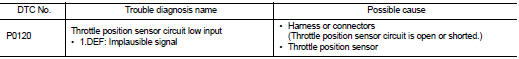
DTC DETECTION LOGIC
Diagnosis Procedure
1.CHECK GROUND CONNECTIONS
1. Turn ignition switch OFF and wait at least 20 seconds.
2. Check ground connection E38. Refer to Ground inspection in GI-44, "Circuit Inspection".
Is the inspection result normal? YES >> GO TO 2.
NO >> Repair or replace ground connection.
2.CHECK THROTTLE POSITION SENSOR POWER SUPPLY CIRCUIT
1. Disconnect electric throttle control actuator harness connector.
2. Turn ignition switch ON.
3. Check the voltage between electric throttle control actuator harness connector and ground.

Is the inspection result normal? YES >> GO TO 3.
NO >> Repair open circuit or short to ground or short to power in harness or connectors.
3.CHECK THROTTLE POSITION SENSOR GROUND CIRCUIT FOR OPEN AND SHORT
1. Turn ignition switch OFF and wait at least 20 seconds.
2. Disconnect ECM harness connector.
3. Check the continuity between electric throttle control actuator harness connector and ECM harness connector.

4. Also check harness for short to ground and short to power.
Is the inspection result normal? YES >> GO TO 4.
NO >> Repair open circuit or short to ground or short to power in harness or connectors.
4.CHECK THROTTLE POSITION SENSOR INPUT SIGNAL CIRCUIT FOR OPEN AND SHORT
1. Check the continuity between electric throttle control actuator harness connector and ECM harness connector.

2. Also check harness for short to ground and short to power.
Is the inspection result normal? YES >> GO TO 5.
NO >> Repair open circuit or short to ground or short to power in harness or connectors.
5.CHECK THROTTLE POSITION SENSOR
Refer to EC-910, "Component Inspection".
Is the inspection result normal? YES >> GO TO 7.
NO >> GO TO 6.
6.REPLACE ELECTRIC THROTTLE CONTROL ACTUATOR
1. Replace electric throttle control actuator.
2. Perform EC-910, "Special Repair Requirement".
>> INSPECTION END
7.CHECK INTERMITTENT INCIDENT
Refer to GI-42, "Intermittent Incident".
>> INSPECTION END
Component Inspection
1.CHECK THROTTLE POSITION SENSOR
1. Turn ignition switch OFF.
2. Reconnect all harness connectors disconnected.
3. Turn ignition switch ON.
4. Check the voltage between ECM harness connector terminals as follows.

Is the inspection result normal? YES >> INSPECTION END
NO >> Replace electric throttle control actuator assembly.
Special Repair Requirement
1.PERFORM THROTTLE VALVE CLOSED POSITION LEARNING
Refer to EC-882, "Work Procedure".
>> END
 P0115 ECT sensor
DTC Logic
DTC DETECTION LOGIC
Diagnosis Procedure
1.CHECK GROUND CONNECTIONS
1. Turn ignition switch OFF.
2. Check ground connection E38. Refer to Ground inspection in GI-44, "Circuit
In ...
 P012A TC boost sensor
DTC Logic
DTC DETECTION LOGIC
Diagnosis Procedure
1.CHECK GROUND CONNECTIONS
1. Turn ignition switch OFF.
2. Check ground connection E38. Refer to Ground inspection in GI-44, "Circuit
In ...
Other materials:
Wiring diagram
MANUAL HEATER SYSTEM
Wiring Diagram
For connector terminal arrangements, harness layouts, and alphabets in a
(option abbreviation; if not
described in wiring diagram), refer to GI-12, "Connector Information/Explanation
of Option Abbreviation".
...
Structure and operation
Sectional View
1. Transfer cover
2. Ring gear shaft
3. Companion flange
4. Drive pinion
5. Ring gear
6. Transfer case
Operation Principle
POWER TRANSFER DIAGRAM
1. Engine
2. Transaxle
3. Transfer
4. Propeller shaft
5. Electric controlled coupling
6. Rear final drive
ELECTR ...
Coil spring
Exploded View
1. Upper rubber seat
2. Coil spring
3. Lower rubber seat
4. Suspension arm
: Vehicle front
Removal and Installation
REMOVAL
1. Remove tires. Refer to WT-7, "Removal and Installation".
2. Remove wheel sensor and sensor harness. Refer to BRC-86, "REAR WHEEL SE ...
