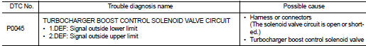
Nissan Juke Service and Repair Manual : P0045 TC boost control solenoid valve
DTC Logic
DTC DETECTION LOGIC
Diagnosis Procedure
1.CHECK TURBOCHARGER BOOST CONTROL SOLENOID VALVE POWER SUPPLY CIRCUIT
1. Turn ignition switch OFF.
2. Disconnect turbocharger boost control solenoid valve harness connector.
3. Turn ignition switch ON.
4. Check the voltage between turbocharger boost control solenoid valve harness connector and ground.

Is the inspection result normal? YES >> GO TO 3.
NO >> GO TO 2.
2.DETECT MALFUNCTIONING PART
Check the following.
• Harness for open or short between IPDM E/R and turbocharger boost control solenoid valve
>> Repair open circuit or short to ground or short to power in harness or connectors.
3.CHECK TURBOCHARGER BOOST CONTROL SOLENOID VALVE OUTPUT SIGNAL CIRCUIT FOR OPEN AND SHORT
1. Turn ignition switch OFF.
2. Disconnect ECM harness connector.
3. Check the continuity between turbocharger boost control solenoid valve harness connector and ECM harness connector.

4. Also check harness for short to ground and short to power.
Is the inspection result normal? YES >> GO TO 4.
NO >> Repair open circuit or short to ground or short to power in harness or connectors.
4.CHECK TURBOCHARGER BOOST CONTROL SOLENOID VALVE
Refer to EC-894, "Component Inspection".
Is the inspection result normal? YES >> GO TO 5.
NO >> Replace turbocharger boost control solenoid valve.
5.CHECK INTERMITTENT INCIDENT
Refer to GI-42, "Intermittent Incident", ???INCIDENT SIMULATION TESTS??? and ???GROUND INSPECTION???.
>> INSPECTION END
Component Inspection
1.CHECK TURBOCHARGER BOOST CONTROL SOLENOID VALVE
1. Turn ignition switch OFF.
2. Disconnect turbocharger boost control solenoid valve harness connector.
3. Check resistance between turbocharger boost control solenoid valve terminals as follows.
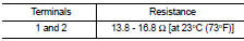
Is the inspection result normal? YES >> INSPECTION END
NO >> Replace turbocharger boost control solenoid valve.
 P0016 CKP - CMP correlation
DTC Logic
DTC DETECTION LOGIC
Diagnosis Procedure
1.CHECK CKP SENSOR AND CMP SENSOR
Refer to EC-932, "Diagnosis Procedure" (CKP sensor) and EC-934, "Diagnosis
Procedure" (C ...
 P0087 fuel pump
DTC Logic
DTC DETECTION LOGIC
NOTE:
• Conditions for applying the diagnostic procedure to the stored DTCs:
The DTC becomes present during the first 30 seconds after the engine starts.
• In low ...
Other materials:
Precaution
Precautions for Suspension
• When installing rubber bushings, the final tightening must be carried out
under unladen conditions with tires
on ground. Spilled oil might shorten the life of rubber bushings. Be sure to
wipe off any spilled oil.
- Unladen conditions mean that fuel, engine coolant ...
B1024 pass A/B deact SW
DTC Logic
DTC DETECTION LOGIC
DTC CONFIRMATION PROCEDURE
1.CHECK SELF-DIAGNOSTIC RESULT
With CONSULT-III
1. Turn ignition switch ON.
2. Perform “Self Diagnostic Result” mode of “AIR BAG” using CONSULT-III.
Without CONSULT-III
1. Turn ignition switch ON.
2. Check the air bag warning lamp ...
Component parts
Component Parts Location
1. Combination meter
Refer to MWI-4, "METER SYSTEM :
Component Parts Location".
2. Combination switch (spiral cable)
3. Driver air bag module
Crash zone sensor
4. Passenger air bag module
5. Seat belt pre-tensioner LH
6. Satellite sensor LH
7. Lap pr ...
