Nissan Juke Service and Repair Manual : Oil cooler
Exploded View
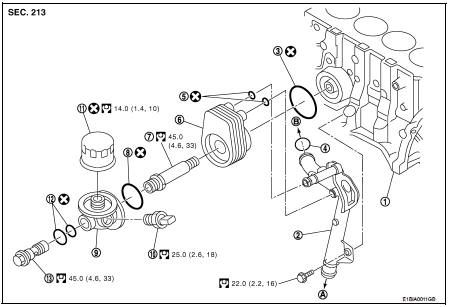
1. Cylinder block
2. Water pipe
3. O-ring
4. O-ring
5. O-ring
6. Oil cooler
7. Connecting stud
8. O-ring
9. Oil filter bracket
10. Oil pressure switch
11. Oil filter
12. O-ring
13. Connecting bolt
A. : To radiator lower hose B. : To water pump
 : N·m (kg-m, ft-lb)
 : Always replace after every
disassembly.
CAUTION:
• Be careful not to get burned when the engine and engine oil are hot.
• When removing, prepare a shop cloth to absorb any oil leakage or spillage.
• Completely wipe off any oil that abhere to the engine and the vehicle.
Removal and Installation
REMOVAL
1. Drain engine coolant. Refer to CO-62, "Draining".
CAUTION:
Perform when engine is cold.
2. Remove oil filter and oil filter bracket. Refer to LU-35, "Exploded View".
3. Remove alternator.
4. Remove oil cooler.
INSTALLATION
Installation is in reverse order of removal.
• Replace the O-ring (A) of the oil cooler, positioning the lip (B) of the seal behind the lug (C) of the oil cooler.

• Confirm that no foreign objects are adhering to the installation planes of the oil cooler and block.
Inspection
Oil Cooler
Check oil cooler for cracks and clogging by blowing through coolant inlet. If
necessary, replace oil cooler
assembly.
 Oil pump
Exploded View
1. Oil pump drive chain
2. Crankshaft sprocket
3. Oil pump assembly
Removal and Installation
REMOVAL
1. Disconnect the battery cable from the negative terminal.
2. Remove eng ...
 Service data and specifications
(SDS)
Service data and specifications
(SDS)
Standard and Limit
OIL PRESSURE
OIL CAPACITY (APPROXIMATE)
TIGHTENING TORQUE
...
Other materials:
Assembly and Installation
• Use torque wrench to tighten bolts or nuts to specification.
• When tightening nuts and bolts, as a basic rule, equally tighten in several
different steps starting with the
ones in center, then ones on inside and outside diagonally in this order. If the
order of tightening is specified,
do ...
Diagnosis and repair work flow
Work Flow
OVERALL SEQUENCE
DETAILED FLOW
1.INTERVIEW FOR MALFUNCTION
Interview the symptom to the customer.
>> GO TO 2.
2.SYMPTOM CHECK
Check the symptom from the customer's information.
>> GO TO 3.
3.BASIC INSPECTION
Check the operation of each part. Check that any sym ...
Rear door
Exploded View
1. Rear door panel
2. Door hinge (upper)
3. Door hinge (lower)
4. Door check link
5. Door striker
6. TORX bolt
: Do not reuse
: N·m (kg-m, in-lb)
N·m (kg-m, ft-lb)
: Body grease
Door assembly
DOOR ASSEMBLY : Removal and Installation
CAUTION:
• Perform work with 2 w ...
