Nissan Juke Service and Repair Manual : Line pressure test
Inspection and Judgment
INSPECTION
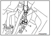
Line Pressure Test Port

Line Pressure Test Procedure 1. Inspect the amount of engine oil and replenish if necessary.
2. Drive the car for about 10 minutes to warm it up so that the CVT fluid reaches in the range of 50 to 80°C (122 to 176°F), then inspect the amount of CVT fluid and replenish if necessary.
NOTE
:
The CVT fluid temperature rises in the range of 50 to 80°C (122 to 176°F) during
10 minutes of driving.
3. After warming up CVT, remove the oil pressure detection plug and install the joint pipe adapter (SST: KV31103600) (A), adapter (SST: 25054000) (B), oil pressure gauge set (commercial service tool) (C).
CAUTION:
When using the oil pressure gauge, be sure to use the Oring
attached to the oil pressure detection plug.
4. Securely engage the parking brake so that the tires do not turn.

5. Start the engine, and then measure the line pressure at both idle and the stall speed.
CAUTION:
• Keep the brake pedal pressed all the way down during
measurement.
• When measuring the line pressure at the stall speed, refer to TM-186, "Inspection and Judgment".
6. After the measurements are complete, install the oil pressure detection plug and tighten to the specified torque below.
 : 7.5 N·m (0.77 kg-m, 66 in-lb)

CAUTION:
• Never reuse O-ring.
• Apply CVT fluid to O-ring.
Line Pressure
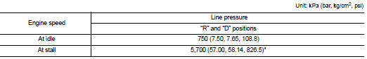
*: Reference values
JUDGMENT

 Stall test
Inspection and Judgment
INSPECTION
1. Inspect the amount of engine oil. Replenish the engine oil if necessary.
2. Drive for about 10 minutes to warm up the vehicle so that the
CVT fluid temperatur ...
 Road test
Description
DESCRIPTION
• The purpose of the test is to determine overall performance of CVT
and analyze causes of problems.
• The road test consists of the following three parts:
1. “Check Befor ...
Other materials:
Hood switch
Component Function Check
1.CHECK FUNCTION
1. Select “HOOD SW” in “Data Monitor” mode of “IPDM E/R” using CONSULT-III.
2. Check “HOOD SW” indication under the following condition.
Is the indication normal?
YES >> Hood switch is OK.
NO >> Go to SEC-223, "Diagnosis Procedure& ...
Wiring diagram
Security control system
LHD
LHD : Wiring Diagram
For connector terminal arrangements, harness layouts, and alphabets in a
(option abbreviation; if not
described in wiring diagram), refer to GI-12, "Connector Information/Explanation
of Option Abbreviation".
RHD
RHD : Wirin ...
B1042, B1043, B1044, B1045, B1046, B1047 diagnosis sensor unit
DTC Logic
DTC DETECTION LOGIC
DTC CONFIRMATION PROCEDURE
1.CHECK SELF-DIAG RESULT
With CONSULT-III
1. Turn ignition switch ON.
2. Perform “Self Diagnostic Result” mode of “AIR BAG” using CONSULT-III.
Without CONSULT-III
1. Turn ignition switch ON.
2. Check the air bag warning lamp statu ...
