Nissan Juke Service and Repair Manual : Fuel level sensor signal circuit
Component Function Check
2WD MODELS
1.CHECK COMBINATION METER OUTPUT SIGNAL
Select the “Data Monitor” for the “METER/M&A” and compare the “FUEL METER” monitor value with the fuel gauge reading on the combination meter.

Does monitor value match fuel gauge reading? YES >> INSPECTION END
NO >> Replace combination meter. Refer to MWI-69, "Removal and Installation".
4WD MODELS
1.CHECK COMBINATION METER OUTPUT SIGNAL
Select the “Data Monitor” for the “METER/M&A” and compare the “FUEL METER” monitor value with the fuel gauge reading on the combination meter.

Does monitor value match fuel gauge reading? YES >> INSPECTION END
NO >> Replace combination meter. Refer to MWI-69, "Removal and Installation".
Diagnosis Procedure
1.CHECK COMBINATION METER INPUT SIGNAL
1. Turn ignition switch ON.
2. Check voltage between combination meter harness connector and ground.

Does it match fuel gauge reading? YES >> GO TO 2.
NO >> Replace the combination meter. Refer to MWI-69, "Removal and Installation".
2.CHECK FUEL LEVEL SENSOR CIRCUIT
1. Turn ignition switch OFF.
2. Disconnect combination meter connector and fuel level sensor unit connector.
3. Check continuity between combination meter harness connector terminal and fuel level sensor unit harness connector terminal.
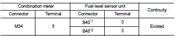
*1: 2WD models
*2: 4WD models
4. Check continuity between combination meter harness connector terminal and ground.
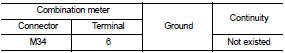
Is the inspection result normal? YES >> GO TO 3.
NO >> Repair harness or connector.
3.CHECK FUEL LEVEL SENSOR GROUND CIRCUIT
Check continuity between fuel level sensor unit harness connector terminal and combination meter harness connector terminal.

*1: 2WD models
*2: 4WD models
Is the inspection result normal? YES >> INSPECTION END
NO >> Repair harness or connector.
Component Inspection
2WD MODELS
1.REMOVE FUEL LEVEL SENSOR UNIT (MAIN)
Remove the fuel level sensor unit (main). Refer to FL-6, "2WD : Removal and Installation" (MR16DDT), FL-33, "Removal and Installation" (HR16DE), or FL-51, "Removal and Installation" (K9K).
>> GO TO 2.
2.CHECK FUEL LEVEL SENSOR UNIT (MAIN)
Check the resistance between fuel level sensor unit and fuel pump.


*: When float rod is contact with stopper.
Is inspection result OK? YES >> INSPECTION END
NO >> Replace the fuel level sensor unit (main). Refer to FL-6, "2WD : Removal and Installation" (MR16DDT), FL-33, "Removal and Installation" (HR16DE), or FL-51, "Removal and Installation" (K9K).
4WD MODELS
1.REMOVE FUEL LEVEL SENSOR UNIT (MAIN)
Remove the fuel level sensor unit (main). Refer to FL-11, "4WD : Removal and Installation".
>> GO TO 2.
2.CHECK FUEL LEVEL SENSOR UNIT (MAIN)
Check the resistance between fuel level sensor unit and fuel pump.


*: When float rod is contact with stopper.
Is inspection result OK? YES >> GO TO 3.
NO >> Replace fuel level sensor unit (main). Refer to FL-11, "4WD : Removal and Installation".
3.REMOVE FUEL LEVEL SENSOR UNIT (SUB)
Remove the fuel level sensor unit (sub). Refer to FL-11, "4WD : Removal and Installation".
>> GO TO 4.
4.CHECK FUEL LEVEL SENSOR UNIT (SUB)
Check the resistance between fuel level sensor unit (sub).


*: When float rod is contact with stopper.
Is inspection result OK? YES >> INSPECTION END
NO >> Replace fuel level sensor unit (sub). Refer to FL-11, "4WD : Removal and Installation".
 Power supply and ground circuit
Combination meter
COMBINATION METER : Diagnosis Procedure
1.CHECK FUSE
Check for blown fuses.
Is the inspection result normal?
YES >> GO TO 2.
NO >> Be sure to eliminate cause of ...
 Oil pressure switch signal circuit
Component Function Check
1.CHECK COMBINATION METER INPUT SIGNAL
Select the “Data Monitor” for the “METER/M&A” and check the “OIL W/L” monitor
value.
“OIL W/L”
Ignition switch ON : On
Engine ...
Other materials:
Upper link
Exploded View
1. Rear suspension member
2. Adjusting bolt
3. Upper link
4. Eccentric disk
5. Lower link
6. Suspension arm bracket
7. Suspension arm
: Vehicle front
: Always replace after every
disassembly.
: N·m (kg-m, ft-lb)
Removal and Installation
REMOVAL
1. Remove tires. WT- ...
Structure and operation
Sectional View
1. 5th input gear
2. 5th-reverse synchronizer hub assembly
3. Input shaft
4. Mainshaft
5. 5th main gear
6. Mainshaft rear bearing
7. 4th main gear
8. 3rd-4th synchronizer hub assembly
9. 3rd main gear
10. 2nd main gear
11. 1st-2nd synchronizer hub assembly
12. Dif ...
Interior room lamp control circuit
Description
Controls each interior room lamp (ground side) by PWM signal.
NOTE:
PWM signal control period is approximately 250 Hz (in the gradual
brightening/dimming).
Component Function Check
CAUTION:
Before performing the diagnosis, check that the following are normal.
• Interior room l ...
