Nissan Juke Service and Repair Manual : Front wiper auto stop signal circuit
Component Function Check
1.CHECK FRONT WIPER (AUTO STOP) SIGNAL
 CONSULT-III DATA MONITOR
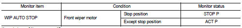
1. Select “WIP AUTO STOP” of IPDM E/R data monitor item.
2. Operate the front wiper.
3. With the front wiper operation, check the monitor status.
Is the status of item normal? YES >> Auto stop signal circuit is normal.
NO >> Refer to WW-40, "Diagnosis Procedure".
Diagnosis Procedure
1.CHECK IPDM E/R OUTPUT VOLTAGE
1. Turn ignition switch OFF.
2. Disconnect front wiper motor connector.
3. Turn ignition switch ON.
4. Check voltage between front wiper motor harness connector and ground.

Is the inspection result normal? YES >> Replace front wiper motor.
NO >> GO TO 2.
2.CHECK FRONT WIPER MOTOR (AUTO STOP) CIRCUIT
1. Turn ignition switch OFF.
2. Disconnect IPDM E/R connector.
3. Check continuity between IPDM E/R harness connector and front wiper motor harness connector.

4. Check continuity between IPDM E/R harness connector and ground.

Is the inspection result normal? YES >> Replace IPDM E/R.
NO >> Repair or replace harness.
 Front wiper motor hi circuit
Component Function Check
1.CHECK FRONT WIPER HI OPERATION
CONSULT-III ACTIVE TEST
1. Select “FRONT WIPER” of IPDM E/R active test item.
2. With operating the test item, check front wiper operation ...
 Front wiper motor ground circuit
Diagnosis Procedure
1.CHECK FRONT WIPER MOTOR GROUND CIRCUIT
1. Turn ignition switch OFF.
2. Disconnect front wiper motor connector.
3. Check continuity between front wiper motor harness connector ...
Other materials:
4WD warning lamp does not turn off
Description
4WD warning lamp does not turn OFF several seconds after the engine started.
Diagnosis Procedure
1.PERFORM SELF-DIAGNOSIS
With CONSULT-III
Perform self-diagnosis for “ALL MODE AWD/4WD”.
Is any DTC detected?
YES >> Check the DTC. Refer to DLN-33, "DTC Index".
N ...
None of the power windows can be operated using any
switch
Diagnosis Procedure
1.CHECK BCM POWER SUPPLY AND GROUND CIRCUIT
Check BCM power supply and ground circuit. Refer to the following.
• With Intelligent Key: Refer to BCS-87, "Diagnosis Procedure".
• Without Intelligent Key: Refer to BCS-155, "Diagnosis Procedure".
Is the i ...
Removal and Installation
REMOVAL
1. Disconnect accelerator pedal position sensor harness connector.
2. Loosen mounting bolts, and remove accelerator pedal assembly.
CAUTION:
• Never disassemble accelerator pedal assembly. Never remove accelerator pedal
position sensor
from accelerator pedal assembly.
• Avoid impac ...
