Nissan Juke Service and Repair Manual : ECU diagnosis information
ABS actuator and electric unit (control unit)
Reference Value
CONSULT-III DATA MONITOR STANDARD VALUE


*1: Confirm tire pressure is standard value.
*2: Refer to “valve operation” in BRC-13, "System Description" for valve operation of each valve.
*3: Refer to BRC-13, "System Description" for ON/OFF conditions of each warning lamp and indicator lamp.
Fail-safe
ABS FUNCTION
ABS warning lamp in combination meter turn ON when a malfunction occurs in system [ABS actuator and electric unit (control unit)]. The control is suspended for ABS function. The vehicle status becomes the same as models without ABS function. However, EBD function is operated normally.
NOTE
:
ABS self-diagnosis sound may be heard the same as in the normal condition,
because self-diagnosis is performed
when ignition switch turns ON and when vehicle initially starts.
EBD FUNCTION
ABS warning lamp and brake warning lamp in combination meter turn ON when a malfunction occurs in system [ABS actuator and electric unit (control unit)]. The control is suspended for ABS function and EBD function.
The vehicle status becomes the same as models without ABS function and EBD function.


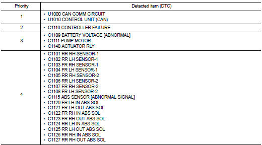
DTC Inspection Priority Chart
When multiple DTCs are displayed simultaneously, check one by one depending on the following priority list.
DTC Index

 Diagnosis system [ABS actuator and electric unit (control
unit)]
Diagnosis system [ABS actuator and electric unit (control
unit)]
CONSULT-III Function
APPLICATION ITEMS
CONSULT-III can display each diagnostic item using the diagnostic test modes
as follows.
*: The following diagnosis information is erased by erasing.
• ...
 Wiring diagram
BRAKE CONTROL SYSTEM
Wiring Diagram
For connector terminal arrangements, harness layout, and alphabets in a
(option abbreviation; if not
described in wiring diagram), refer to GI-12, "Connec ...
Other materials:
Door cable
Exploded View
LEFT SIDE
1. Heater unit assembly
2. Intake door lever
3. Intake door link
4. Intake door cable
5. Air mix door cable
6. Air mix door link
7. Air mix door rod
8. Lower air mix door lever
9. Upper air mix door lever
10. Max. cool door
A. To A/C control
RIGHT SIDE
...
Wiring diagram
EXTERIOR LIGHTING SYSTEM
Wiring Diagram
For connector terminal arrangemants, harness layouts, and alphabets in a
(option abbreviation: if not
described in wiring diagram), refer to GI-12, "Connector Information/Explanation
of Option Abbreviation".
...
All defogger system dose not operate
Description
Rear window defogger and door mirror defogger do not operate when rear window
defogger switch operated.
Diagnosis Procedure
1.CHECK REAR WINDOW DEFOGGER SWITCH
Check rear window defogger switch.
Refer to DEF-26, "WITH AUTO A/C : Component Function Check" (With Auto A/C ...
